
Backlight module assembly

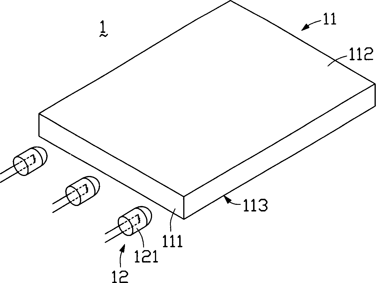
A backlight module and light source technology, applied in optics, nonlinear optics, diffuser elements, etc., can solve problems such as low brightness and large loss of light energy, and achieve the effect of improving brightness

Inactive Publication Date: 2006-07-12
INNOCOM TECH SHENZHEN +1
View PDF1 Cites 18 Cited by
  • Summary
  • Abstract
  • Description
  • Claims
  • Application Information

AI Technical Summary

Problems solved by technology

[0008] In order to overcome the problems of large light energy loss and low brightness in the prior art backlight module, the present invention provides a backlight module with small energy loss and high brightness

Method used


Image

  • Backlight module assembly
  • Backlight module assembly
  • Backlight module assembly

Examples


Embodiment Construction

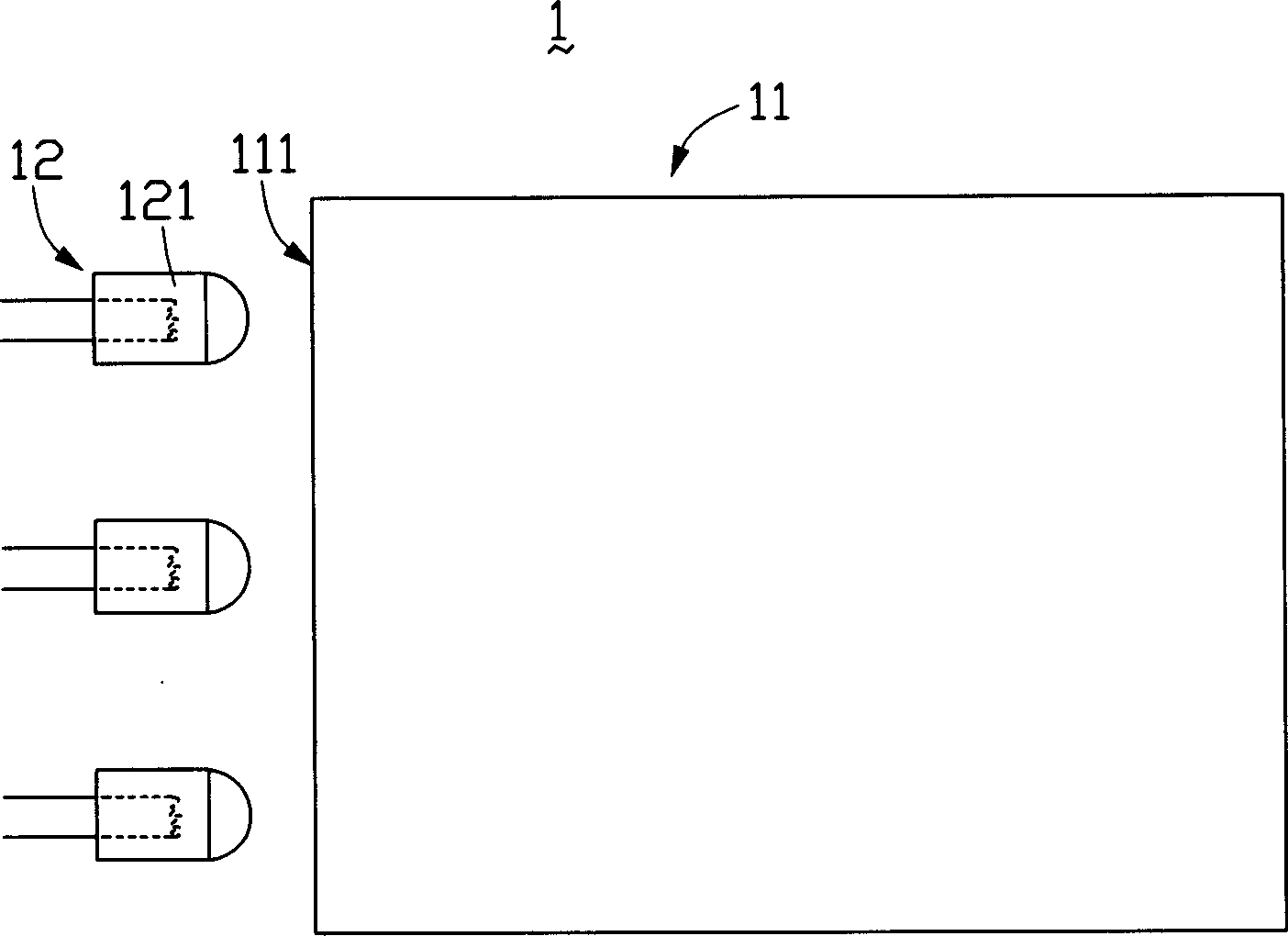
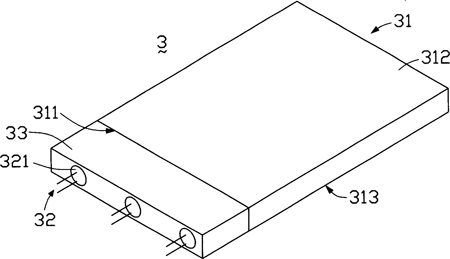
[0015] see image 3 and Figure 4 , is a perspective view and a plan view of the first embodiment of the backlight module of the present invention, the backlight module 3 includes a light guide plate 31 and a plurality of point light sources 32 . The light guide plate 31 is a flat light guide plate made of transparent materials such as acrylic, glass or polycarbonate, and includes a light incident surface 311, a light exit surface 312 vertically connected to the light incident surface 311, and a light exit surface. The bottom surface 313 opposite the surface 312 . The plurality of point light sources 32 are arranged at equal intervals on the side of the light incident surface 311 of the light guide plate 31. In order to protect the point light sources 32 from damage, the surface of the point light sources 32 is covered with an encapsulating resin 321, which can be configured by arranging a plurality of different colors. The point light source 32 can adjust the required light...


PUM


Abstract

The invention discloses a negative phototropic mould, which consists of light conducting plate and at least one point light source, wherein the light conducting plate contains a light inlet face, a light outlet face and a soffit corresponding to the light outlet face; the point light source is set near the light conducting plate, whose surface is covered by packing resin to protect the point light source; the resin is filled between the point light source and light inlet face, which makes the refractive index of resin more than the air dielectrics' to reduce the light energy loss and improve the brightness of negative phototropic mould.

Description

【Technical field】 [0001] The invention relates to a backlight module used for a liquid crystal display. 【Background technique】 [0002] Due to the advantages of lightness, thinness, and low power consumption, liquid crystal displays are widely used in modern information equipment such as notebook computers, mobile phones, and personal digital assistants. Because the liquid crystal itself does not have light-emitting properties, it is necessary to provide a backlight module for it to realize the display function. [0003] The existing backlight module includes a light source and a light guide plate. The light source is arranged relative to the light incident surface of the light guide plate. The light guide plate guides the transmission direction of the light beam emitted from the light source, and converts the line light source or point light source into a surface light source for emission. A plurality of dots are distributed on the bottom surface of the light guide plate t...

Claims


Application Information

Patent Timeline
Patent Type & Authority Applications(China)
IPC IPC(8): G02F1/1335G02B5/02
Inventor 黄柏山郭帅梁亚丹
Owner INNOCOM TECH SHENZHEN
Learn More