Novel permanent-magnet machine

A permanent magnet motor, a new type of technology, applied in the direction of magnetic circuit static parts, magnetic circuit shape/style/structure, etc., can solve complex problems, and achieve the effect of improving starting performance, simple structure, and reducing starting torque

Inactive Publication Date: 2006-07-12
李国坤
0 Cites 1 Cited by

AI-Extracted Technical Summary

Problems solved by technology

There have been literatures introducing the use of some extremely complicated technical means and mea...

Abstract

The invention relates to an improved p-m motor, which comprises a rotor with permanent magnet, a stator with winding, and a thin-wall magnetic-conduction metal ring on inner circle of stator with axial length same as the stator.

Application Domain

Technology Topic

Image

  • Novel permanent-magnet machine
  • Novel permanent-magnet machine

Examples

  • Experimental program(1)

Example Embodiment

[0009] The present invention is explained below in conjunction with accompanying drawing:
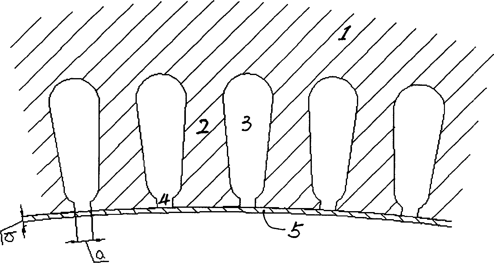
[0010] attached figure 2 It is an embodiment of the present invention. The difference between the present invention and the prior art can be seen more clearly.
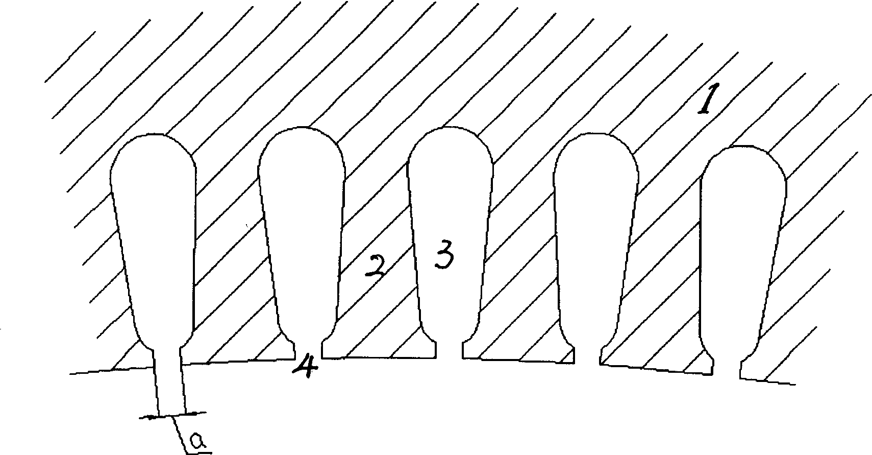
[0011] attached figure 1 It is a partial cross-sectional view of the stator part of the existing permanent magnet motor. The stator 1 is provided with alternate teeth 2 and slots 3, and the space of the slot 3 is used for placing windings.
[0012] attached figure 2 It is a partial sectional view of the stator part of the permanent magnet motor of the present invention, from figure 2 It can be seen that the present invention is different from the prior art only in that a metal thin-walled ring 5 closely contacting with the stator for magnetic conduction is arranged at the inner circle of the stator 1, and the axial length of the ring is equal to the axial length of the stator. The tight contact mentioned here refers to the conduction of the magnetic circuit between the ring and the stator. Generally speaking, the ring 5 can be made of soft iron or metal with low carbon content. According to relevant tests, the radial thickness of the ring of the present invention can be 1/7-1/3 of the width of the opening 4 at the lower end of the stator slot.
[0013] An example of the present invention is a permanent magnet motor with a power of 300W. When the motor adopts the existing technology, that is, the stator is figure 1 When the structure is shown, the measured starting torque of the motor is 0.102N·M. And adopt the structure of the present invention, promptly adopt the attached figure 2 With the structure shown, the starting torque of the motor is reduced to 0.065N·M, which is 36% lower than that of the existing permanent magnet motor.

PUM

no PUM

Description & Claims & Application Information

We can also present the details of the Description, Claims and Application information to help users get a comprehensive understanding of the technical details of the patent, such as background art, summary of invention, brief description of drawings, description of embodiments, and other original content. On the other hand, users can also determine the specific scope of protection of the technology through the list of claims; as well as understand the changes in the life cycle of the technology with the presentation of the patent timeline. Login to view more.

Similar technology patents

Secondary pendulum chaotic vibration motor

ActiveCN101982926ASmall starting torqueImprove speed and reliabilityMechanical energy handlingPhysicsStator
Owner:NANJING INST OF TECH

Spiral combined paddle for vertical-axis wind power generator

PendingCN107725270ASmall starting torqueGuaranteed continuityRenewable energy generationMachines/enginesWind forceAutomotive engineering
Owner:黑龙江镁图科技开发有限公司

Energy-saving steam turbine generator set utilizing low-pressure saturated steam to generate electricity

InactiveCN109611162AReduce radial sizeSmall starting torqueBlade accessoriesMachines/enginesDischarge pressureDynamo
Owner:北京康吉森节能环保技术有限公司

Classification and recommendation of technical efficacy words

  • Small starting torque
  • Improve starting performance

Magnetic liquid sealing device

InactiveCN112212011AReduce injection volumeSmall starting torqueEngine sealsPhysicsMagnetic liquids
Owner:TSINGHUA UNIV

Planetary gear speed increaser

InactiveCN104482129ASmall starting torqueSmall and compactToothed gearingsPhysicsAerospace engineering
Owner:SHANDONG ZHENGHAO MECHANICAL EQUIP

Water-land amphibious barrel-shaped robot

InactiveCN104842726ASmall starting torqueReduce energy consumptionAmphibious vehiclesWorking capacityEngineering
Owner:NORTHWESTERN POLYTECHNICAL UNIV

Engine starter

InactiveCN1459560AImprove starting performanceControlled back swingElectrical controlElectric motor startersElectric machineryTop dead center
Owner:HONDA MOTOR CO LTD

Method for estimating precise position of electro-magnetic doubly salient motor rotor

ActiveCN106787997AImprove commutation accuracyImprove starting performanceElectronic commutation motor controlPhysicsInductor
Owner:NANJING UNIV OF AERONAUTICS & ASTRONAUTICS

UV enhancer for discharge lamp and manufacturing method thereof

ActiveUS20120181924A1Improve starting performanceAvoid crackingElectroluminescent light sourcesCold-cathode tubesGlow dischargeEngineering
Owner:IWASAKI ELECTRIC CO LTD
Why Eureka
Try Eureka