Cement clinker grinding implementation equipment and stirring device thereof

A technology of cement clinker and mixing device, which is used in transportation and packaging, dissolving, grain processing, etc., to reduce energy consumption, eliminate dead material areas, and increase production capacity.

Pending Publication Date: 2019-11-15
CHENGDU LEEJUN IND +1
View PDF3 Cites 7 Cited by
  • Summary
  • Abstract
  • Description
  • Claims
  • Application Information

AI Technical Summary

Problems solved by technology

[0008] The purpose of the present invention is to solve the problem that the existing horizontal ball mill is not suitable for cement clinker dry grinding, especially the problem that the existing horizontal ball mill has a large number of dead material areas under the condition of high filling and high speed. The present invention provides a A kind of cement clinker grinding implementation equipment, which can carry out dry grinding under the condition of high filling rate and high speed, effectively eliminate dead material area, and greatly reduce energy consumption under the condition of grinding materials of the same level

Method used


Image

  • Cement clinker grinding implementation equipment and stirring device thereof
  • Cement clinker grinding implementation equipment and stirring device thereof
  • Cement clinker grinding implementation equipment and stirring device thereof

Examples


Embodiment 1

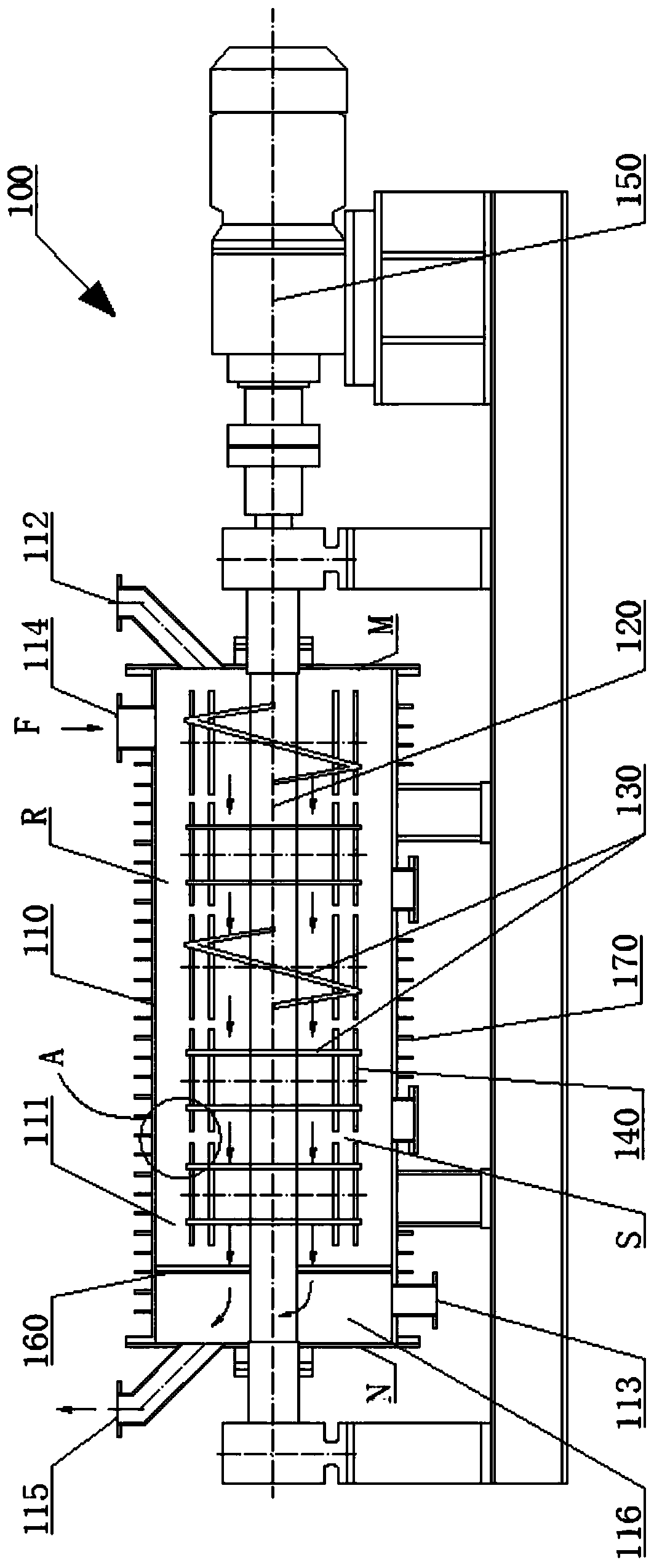
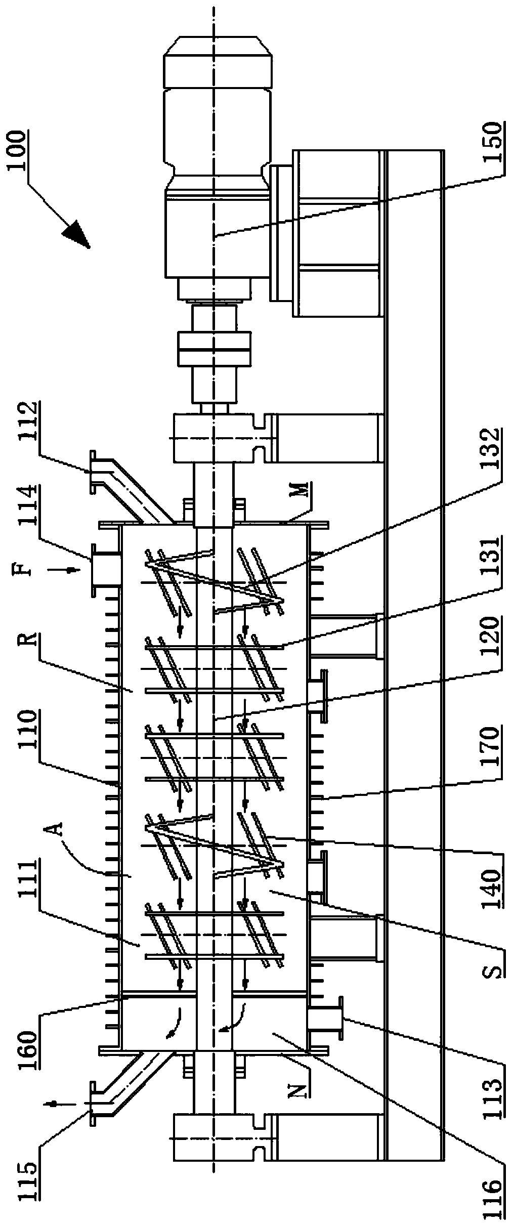
[0043] refer to figure 1 Illustrate the stirring device according to the cement clinker grinding implementation equipment 100 disclosed in this embodiment, which includes a stirring shaft 120, a stirring unit 130 and a reinforcing stirring member 140, the stirring unit 130 is installed on the stirring shaft 120, the stirring unit 130 and the stirring shaft 120 is preferably connected by keys or bolts, and the reinforcing stirring member 140 is installed on the stirring unit 130, and the number of the stirring unit 130 and the reinforcing stirring member 140 is at least one. When the number of stirring units 130 is greater than 1, the stirring units 130 are arranged in sequence along the axial direction of the stirring shaft 120 .

[0044] When the stirring shaft 120 rotates, the stirring unit 130 rotates together with the stirring shaft 120 . The stirring unit 130 protrudes from the stirring shaft 120 radially along the stirring shaft 120 and is the main functional element of...

Embodiment 2

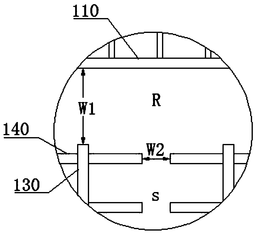
[0052] refer to figure 1 Explain that the cement clinker grinding implementation equipment 100 disclosed in this embodiment includes a housing 110, a screening device 160 and a stirring device, including a stirring shaft 120 that can be driven to rotate by a drive system 150, and a shaft that is arranged on the stirring shaft 120 Upward at least one stirring unit 130, the two sides of the stirring unit 130 along the axial direction of the stirring shaft 120 form a sub-grinding area S, at least one strengthening stirring piece 140 is connected to the stirring unit 130, and the strengthening stirring piece 140 is in the sub-grinding area S Extending in the grinding zone S, the reinforcing stirring member 140 cooperates with the stirring unit 130 to make at least part of the grinding media and materials in the sub-grinding zone S perform grinding motion along the circumference of the stirring shaft 120 . The housing 110 includes a wall defining a horizontally extending stirring c...


PUM


Abstract

The invention discloses cement clinker grinding implementation equipment, and relates to the technical field of grinding devices. The cement clinker grinding implementation equipment comprises a shell, a rotatable stirring shaft, stirring units, a screening device and reinforced stirring parts, wherein the stirring shaft is inserted into a stirring cavity of the shell, the stirring units are arranged on the stirring shaft, the screening device separates the stirring cavity and a discharge port, and the reinforces stirring parts extend in a sub-grinding area; and the reinforced stirring parts are configured to enable at least part of grinding media and materials of the sub-grinding area to do grinding motion in the circumferential direction of the stirring shaft in cooperation with the stirring units. According to the cement clinker grinding implementation equipment, dry grinding can be carried out under the conditions of high filling ratio and high rotating speed, the dead mass zone iseffectively eliminated, and the energy consumption is greatly reduced under the condition of grinding the materials with the equal magnitude.

Description

technical field [0001] The invention relates to the technical field of grinding devices, in particular to cement clinker grinding equipment and a stirring device thereof. Background technique [0002] The high-energy ball mill is the core equipment of the crushing and grinding process. The drum-type ball mill mainly used in industry has a large processing capacity, but it has a critical speed and the collision energy is small during ball milling. The cylinder part of the stirring ball mill is fixed, and the agitator rotates at high speed with the main shaft. Under the action of friction and centrifugal force, the grinding medium in the cylinder is driven to move together, so that intense and frequent collisions occur between the medium and between the medium and the wall. Shearing and friction, resulting in the crushing and dissociation of materials. In principle, the stirring ball mill has no speed limit, and the collision energy can reach a large value during ball milling...

Claims


Application Information

Patent Timeline
Patent Type & Authority Applications(China)
IPC IPC(8): B02C17/16B02C17/18B02C17/10B01F13/10
CPCB02C17/10B02C17/163B02C17/16B02C2017/165B01F33/8305B01F33/83613
Inventor 何亚民丁亚卓徐智平
Owner CHENGDU LEEJUN IND
Why Eureka
Try Eureka