Wind-collection supercharged type magnetic-suspension vertical wind power generation system

A wind power generation system and wind collection technology, applied in the direction of wind power generators, wind power generators at right angles to the wind direction, and wind power motor combinations, etc., can solve problems such as easy to be destroyed by storms, small working wind area, and large impact on the power grid. To achieve the effect of increasing power generation capacity and utilization efficiency of wind resources, maintaining continuity and stability, and increasing wind drive torque

Active Publication Date: 2017-02-22
李树广
View PDF15 Cites 7 Cited by
  • Summary
  • Abstract
  • Description
  • Claims
  • Application Information

AI Technical Summary

Problems solved by technology

[0008] Aiming at the deficiencies in the prior art, the present invention provides a wind-gathering and pressurized maglev vertical wind power generation system to solve the problem of small wind-receiving area of ​​the wind blades, low wind utilization rate, and large wind resistance of the front airfoil in the...

Method used


Image

  • Wind-collection supercharged type magnetic-suspension vertical wind power generation system
  • Wind-collection supercharged type magnetic-suspension vertical wind power generation system
  • Wind-collection supercharged type magnetic-suspension vertical wind power generation system

Examples


Embodiment approach

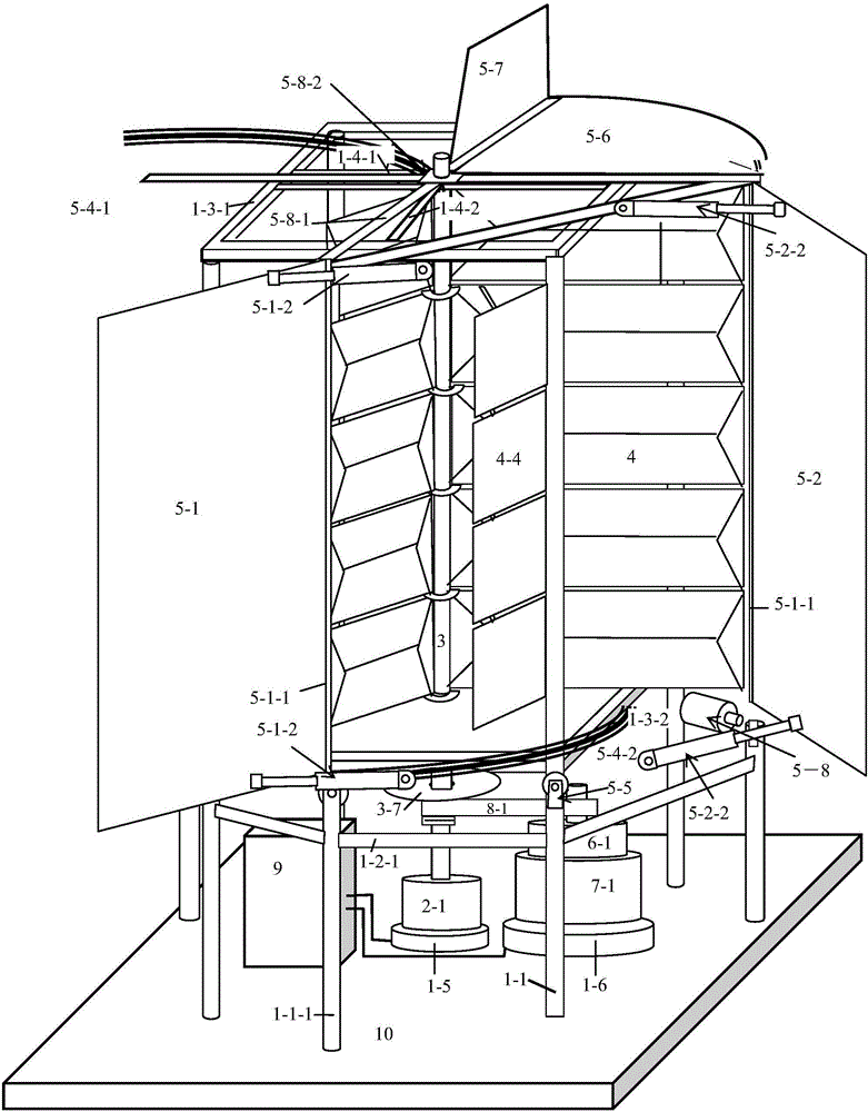
[0114] In this embodiment: the main body of the system frame is composed of the frame column 1-1, the lower beam 1-2 and the upper beam 1-2, Figure 9 and Figure 12 The lower track 5-4-2 of the air collection and booster system shown is installed outside the four columns 1-1 of the system frame Figure 12 The support piece and the auxiliary support column 1-1-1.

[0115] Figure 14 The schematic diagram of the structure of the supporting member 5-5 is shown. 5-5 in the figure is fixed on the fixed column 1-1, 5-5-1 is the supporting shaft, 5-5-2 is the pulley, and the lower track 5-4-2 is installed on the pulley, and the rudder plate 5 of the wind collecting system -7 It is estimated that the steering drive device 5-9 drives the rack mounted on the lower track 5-4-2 5-4-3 to estimate that the wind collection system 5 follows the wind direction and rotates, so that the wind collection booster protection system can track the wind direction Rotate under control system 9 cont...


PUM


Abstract

The invention provides a wind-collection supercharged type magnetic-suspension vertical wind power generation system. The wind-collection supercharged type magnetic-suspension vertical wind power generation system comprises a main body frame, a generator, a control system, a pushing magnetic-suspension bearing, a multiple-section combined shaft mounted on the pushing magnetic-suspension bearing, a combined blade mounted on the combined shaft and an automatic-steering wind collection protection system. The automatic-steering wind collection protection system comprises a wind collection rotating frame mounted on the main body frame, a left wind collection plate, a right wind collection plate, a wind-accumulation supercharging plate, a wind collection rudder plate and a wind collection system steering driving device, wherein the left wind collection plate and the right wind collection plate are mounted windward. The wind collection rudder plate and the wind collection system steering driving device push the wind collection rotating frame to rotate along with the wind direction, and drive the left wind collection plate and the right wind collection plate to always face the front wind direction, and accordingly, the maximum wind collection quantity and the maximum continuous wind power driving torque are acquired. The wind collection system always rotates windward, dead angle is avoided, the wind collection quantity is maximized, and power generation capacity and wind resource utilization efficiency of the wind power generator are increased.

Description

technical field [0001] The invention relates to a vertical wind power generation system, in particular to a wind collecting and boosting type maglev vertical wind power generation system, which belongs to the technical field of wind power generation. Background technique [0002] With the occurrence of the world energy crisis, the use of wind kinetic energy as a new energy source has become a hot spot in the development of modern society. The generator set and the speed increaser of the traditional three-bladed wind turbine are installed high above the top of the tower, and the heavy wind blades are hung obliquely on the side, which requires a heavy counterweight. Considering that the wind blades, speed increaser, generator set, counterweight body and heavy engine room have a weight of hundreds of tons, they are supported at high altitude by the tower, and when the storm blows, a huge blowing and overturning moment is generated, which is easy to be destroyed. Storm blows da...

Claims


Application Information

Patent Timeline
IPC IPC(8): F03D9/25F03D80/70F03D15/00F03D3/06
CPCY02E10/74F03D3/062
Inventor 李树广
Owner 李树广
Why Eureka
Try Eureka