Bearing device for wheel

A technology for bearing devices and wheels, which is applied in bearing assembly, bearing components, shafts and bearings, etc., can solve the problems of not developing bearing devices, and achieve the effects of improving fuel consumption and suppressing inclination

Inactive Publication Date: 2006-07-12
NTN CORP
View PDF0 Cites 6 Cited by
  • Summary
  • Abstract
  • Description
  • Claims
  • Application Information

AI Technical Summary

Problems solved by technology

However, a bearing device that can variably set the optimum bearing preload according to the driving conditions of the vehicle has not been developed

Method used


Image

  • Bearing device for wheel
  • Bearing device for wheel
  • Bearing device for wheel

Examples


no. 1 example

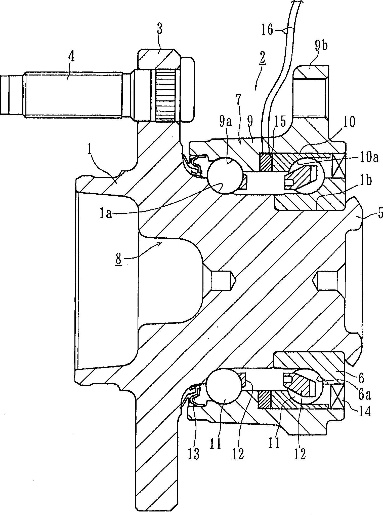
[0041] Preferred embodiments of the present invention will be described below with reference to the accompanying drawings. figure 1 A first embodiment of the bearing device for a wheel of the present invention is shown.

[0042] The bearing device for a wheel is used for a driven wheel, and includes a wheel hub 1 and a double row rolling bearing 2 . In the following description, the term "outside" of the device (left-hand side in the figure) refers to the side that is located outside the vehicle body when the bearing device is installed on the vehicle body, while the term "inside" of the device (inside the The right-hand side in ) refers to the side that is located inside the vehicle body when the bearing unit is installed on the vehicle body.

[0043] The wheel hub 1 is integrally formed with: a wheel mounting flange 3 at one end on the outer side; an outer side inner raceway surface 1a of a double row rolling bearing 2 on its outer peripheral surface; and a column axially ...

no. 2 example

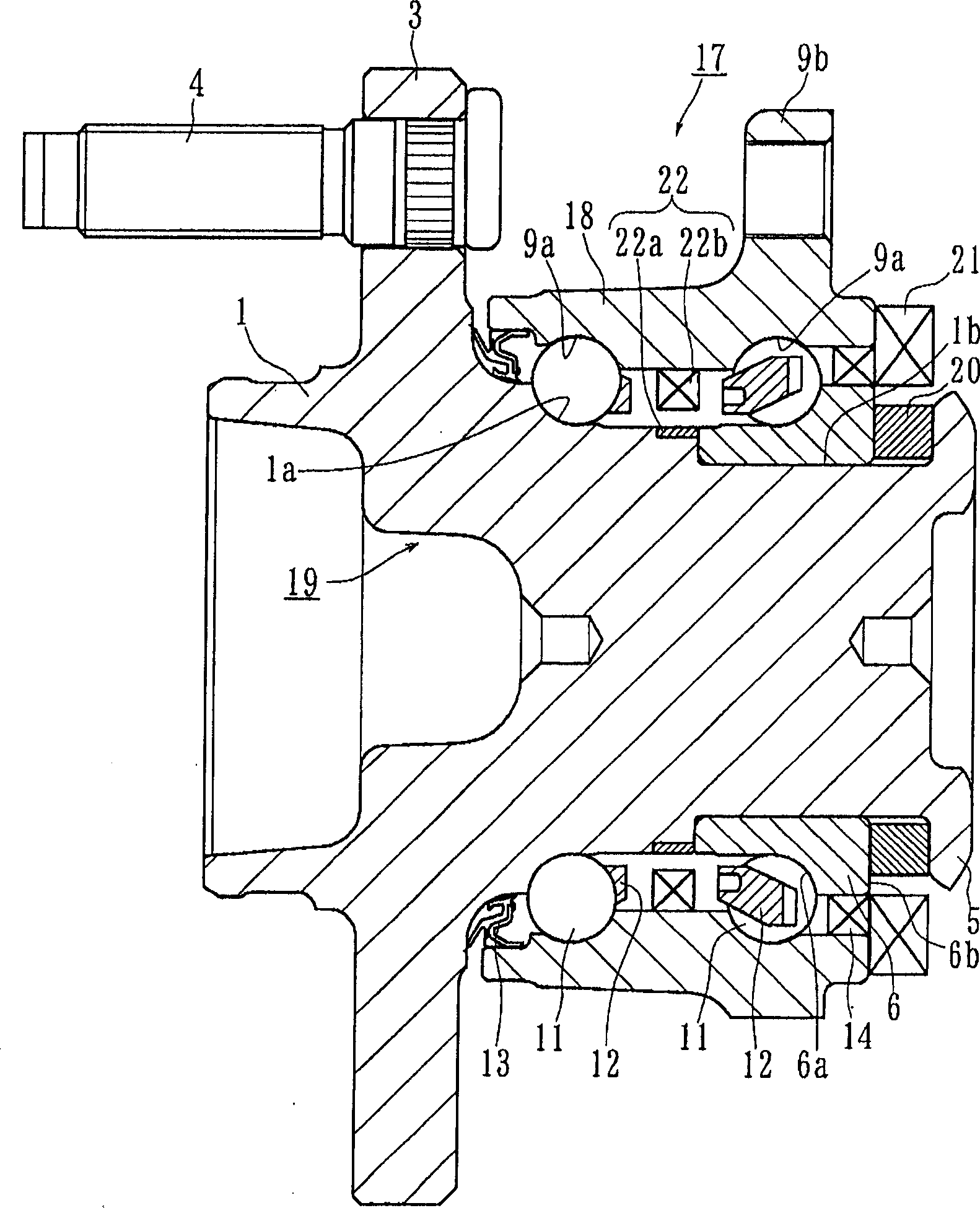
[0048] figure 2 It is a longitudinal sectional view showing a second embodiment of the bearing device for a wheel according to the present invention. In this embodiment, the same reference numerals are used to denote the same components having the same functions as those used in the first embodiment.

[0049] This bearing arrangement for a wheel comprises a wheel hub 1 and a double row rolling bearing 17 comprising an outer part 18 , an inner part 19 and double row rolling elements 11 and 11 . The outer member 18 is integrally formed on its outer peripheral surface with a main body mounting flange 9b for mounting the bearing device on a vehicle body (not shown), and on its inner peripheral surface is formed with a double-row outer raceway surface 9a and 9a.

[0050] A separate inner ring 6 is press-fitted on the axially extending portion 1b of the wheel hub 1 and fixed thereto by means of the caulked portion 5 . Double-row rolling elements 11 and 11 are accommodated betwee...

no. 3 example

[0056] Figure 4 It is a longitudinal sectional view showing a third embodiment of the bearing device for a wheel according to the present invention. In this embodiment, the same reference numerals are used to denote the same components having the same function as those used in the second embodiment, since this embodiment differs from the second embodiment only in its preload application structure.

[0057] This bearing arrangement for a wheel comprises a hub wheel 23 and a double row rolling bearing 24 , and this double row rolling bearing 24 comprises an outer part 18 , an inner part 25 and double row rolling elements 11 and 11 . The outer member 18 is integrally formed on its outer peripheral surface with a main body mounting flange 9b for mounting the bearing device on a vehicle body (not shown), and on its inner peripheral surface is formed with a double-row outer raceway surface 9a and 9a. A separate inner ring 6 is press-fitted on the axially extending portion 1 b of...


PUM


Abstract

A bearing apparatus for a wheel of vehicle comprising a hub wheel integrally formed therewith a wheel mounting flange on the periphery at one end thereof, and a double row rolling bearing, the double row rolling bearing comprising an outer member integrally formed therewith a body mounting flange on the periphery thereof and also formed therewith double row outer raceway surfaces, an inner member including said hub wheel and formed therewith double row inner raceway surfaces each arranged opposite to each of said double row outer surfaces, and double row rolling elements freely rotatably contained between said double row outer and second raceway surfaces, said double row rolling bearing being adapted to be applied a predetermined preload characterized in that: there are arranged a separate outer or inner ring on at least one of said outer and inner members, and a preload varying means arranged at an abutting portion between said outer and inner members for varying the preload applied to the bearing, said preload varying means can be extended or contracted based on an output signal from a detecting sensor for detecting the running condition of vehicle.

Description

technical field [0001] The present invention relates to a bearing device for a wheel for rotatably supporting a wheel of a vehicle (such as an automobile), and more particularly to a bearing device for a wheel in which a preset A load changing device for variably setting an optimum preload suitable for a running condition of the vehicle. Background technique [0002] The power transmission device used to transmit engine power to the wheels needs to allow not only power transmission from the engine to the wheels, but also allow radial and axial changes of the wheels due to bouncing of the vehicle body during driving on uneven roads and during cornering of the vehicle. Displacement and momentum displacement (momentum displacement). Therefore, if Figure 12 As shown, one end of a drive shaft 100 arranged between an engine and drive wheels is connected to a differential device 102 through a sliding type constant velocity universal joint 101, and the other end of the drive shaft...

Claims


Application Information

Patent Timeline
Patent Type & Authority Applications(China)
IPC IPC(8): F16C25/08F16C41/00
Inventor 冈田浩一林丰岩本宪市小池孝志
Owner NTN CORP
Why Eureka
Try Eureka