
Separator for fuel battery

A fuel cell and separator technology, applied in fuel cells, fuel cell parts, circuits, etc., can solve the problems of gasket forming groove damage, stress concentration, damage, etc.

Active Publication Date: 2006-07-12
NOK CORP
View PDF2 Cites 5 Cited by
  • Summary
  • Abstract
  • Description
  • Claims
  • Application Information

AI Technical Summary

Problems solved by technology

[0005] However, when the gasket is integrally formed on the separator body, since silicone rubber is a low-viscosity liquid, it can be molded under low injection pressure without damaging the separator. However, if EPDM and fluorine-containing rubber are used , due to the high viscosity of rubber, it is inevitable to require high injection pressure, so if Figure 10 As shown, the problem that the bottom surface 10a and 11a of the gasket molding groove is broken down due to the pressure of the rubber occurs, and the corner part 14 of the bottom surface of the groove is broken down due to the pressure of the rubber due to the low strength of the side surface of the gasket molding groove, and the damaged part 15 occurs. Therefore, there is a problem of damage to the seal due to damage to the main body of the separator
[0006] In addition, in order to reduce the size and weight of the fuel cell, the main body of the separator is made thinner and thinner, and there is a problem that the bottom surface of the molding groove and the corner of the groove bottom surface are damaged when the liquid rubber is molded under low injection pressure.
In addition, even for gaskets without openings, the bottom surface of the gasket molding grooves may be damaged due to stress concentration caused by forming grooves such as molding grooves and adhesive grooves on the back of the gasket molding grooves during injection molding of rubber, etc. The problem

Method used


Image

  • Separator for fuel battery
  • Separator for fuel battery
  • Separator for fuel battery

Examples


no. 1 example

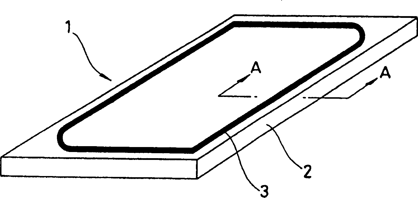
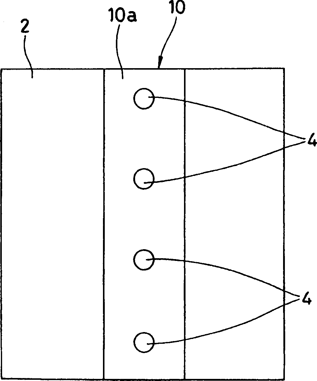
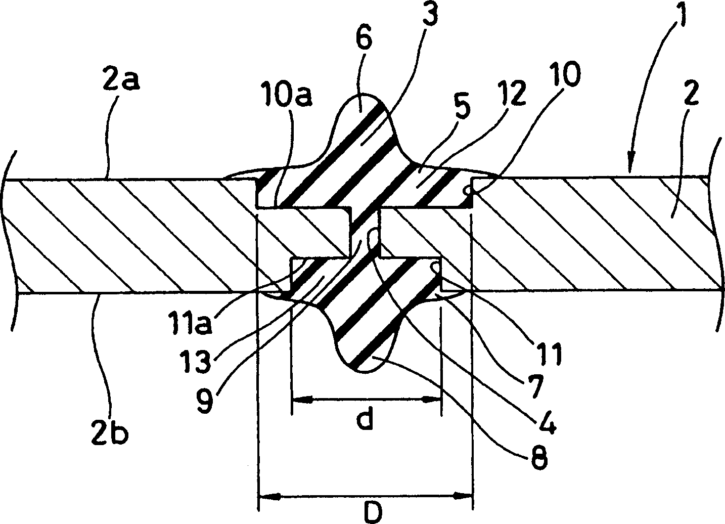
[0056] figure 1 It is a perspective view of the fuel cell separator 1 involved in the first embodiment of the present invention, figure 2 It is a plan view of a part of the separator main body 2 constituting the fuel cell separator 1, image 3 is along figure 1 Partial sectional view of line A-A in middle.

[0057] The fuel cell separator 1 used in this first embodiment, as figure 1 As shown, there are two independent constituent elements of the separator main body 2 and the gasket 3, and the composition of these two elements is as follows.

[0058] That is, first, the gasket forming groove 10 and the gasket forming groove 11, such as figure 2 As shown, each is formed along the extending direction of the gasket on both sides of the separator main body 2 which is compression-molded from a mixture of carbon powder and thermosetting resin phenol, namely 2a and 2b, and is made along the two molding grooves 10 and 11. A desired number of through holes 4 communicate with t...

no. 2 example

[0061] Figure 4 It is a partial cross-sectional view of a fuel cell separator 1 according to a second embodiment of the present invention. The fuel cell separator 1 used in the second embodiment has two independent structures of a separator main body 2 and a gasket 3 components, the composition of these two components is as follows.

[0062] That is, first, the gasket forming groove 10 and the gasket forming groove 11, such as figure 2 As shown, each is formed along the extending direction of the gasket on both sides of the separator main body 2 which is compression-molded from a mixture of carbon powder and thermosetting resin phenol, namely 2a and 2b, and is made along the two molding grooves 10 and 11. A desired number of through holes 4 communicate with the bottom surfaces 10 a and 10 b of the two shaped grooves 10 and 11 . Here, if Figure 4 As shown, the groove side surfaces 16 and 17 of the molding grooves 10 and 11 formed on the two surfaces of the separator main ...

no. 3 example

[0065] Figure 5 It is a partial cross-sectional view of a fuel cell separator 1 related to the third embodiment of the present invention. The fuel cell separator 1 used in the second embodiment has two independent structures of a separator main body 2 and a gasket 3 components, the composition of these two components is as follows. That is, first, the gasket forming groove 10 and the gasket forming groove 11, such as figure 2 As shown, each is formed along the extending direction of the gasket on both sides of the separator main body 2 which is compression-molded from a mixture of carbon powder and thermosetting resin phenol, namely 2a and 2b, and is made along the two molding grooves 10 and 11. A desired number of through holes 4 communicate with the bottom surfaces 10 a and 10 b of the two shaped grooves 10 and 11 . Here, if Figure 5 As shown, the corner portions 14 of the bottom surfaces of the grooves 10 and 11 formed on the two surfaces of the separator main body 2,...


PUM


Abstract

A separator for a fuel battery, where gasket is formed integrally with a separator body by forming rubber in gasket forming grooves provided in the separator body. When rubber is formed in the grooves, damage to the grooves can be constrained, and this prevents lowering of sealing ability caused by damage to the separator. The width of a gasket forming groove formed in one surface of the separator body is greater than a gasket forming groove formed in the other surface. Groove side-surfaces in a gasket forming groove has an inclined shape or a curvature is provided on square corners of groove bottom surfaces.

Description

technical field [0001] The present invention relates to a separator for a fuel cell. Background technique [0002] A solid polymer fuel cell is a battery that uses the principle of generating electricity from hydrogen and oxygen (air) to generate water. The fuel cell is composed of a fuel cell stack (stack) formed by stacking multiple layers of components consisting of an electrolyte membrane permeable to hydrogen ions and two separators sandwiching the electrolyte membrane. In addition, separators constituting the module are required to have the ability to shield hydrogen and oxygen and to conduct electric current. [0003] In addition, hydrogen, oxygen, and cooling water are used in the fuel cell stack. In order to seal these substances, a gasket needs to be installed in the stack. The invention recorded in Kai 2001-185174 proposes a method of integrally forming the gasket on the surface of the separator main body, and proposes to prevent the edge of the gasket from bein...

Claims


Application Information

Patent Timeline
Patent Type & Authority Applications(China)
IPC IPC(8): H01M8/02F16J15/00F16J15/08F16J15/12
CPCH01M8/0258H01M8/0273F16J15/0818H01M8/0284F16J15/122Y02E60/50F16J2015/0856H01M8/0276H01M8/2483H01M8/026H01M8/02
Inventor 井上智广渡部茂浦川哲也
Owner NOK CORP
Learn More