Supercritical pressure regulation of economized refrigeration system.

一种制冷系统、制冷剂的技术,应用在制冷机、制冷组件、制冷和液化等方向

Inactive Publication Date: 2006-07-19
CARRIER CORP
View PDF0 Cites 5 Cited by
  • Summary
  • Abstract
  • Description
  • Claims
  • Application Information

AI Technical Summary

Problems solved by technology

On the downside, the vast majority of these fluids are problematic to use

Method used


Image

  • Supercritical pressure regulation of economized refrigeration system.
  • Supercritical pressure regulation of economized refrigeration system.
  • Supercritical pressure regulation of economized refrigeration system.

Examples


Embodiment Construction

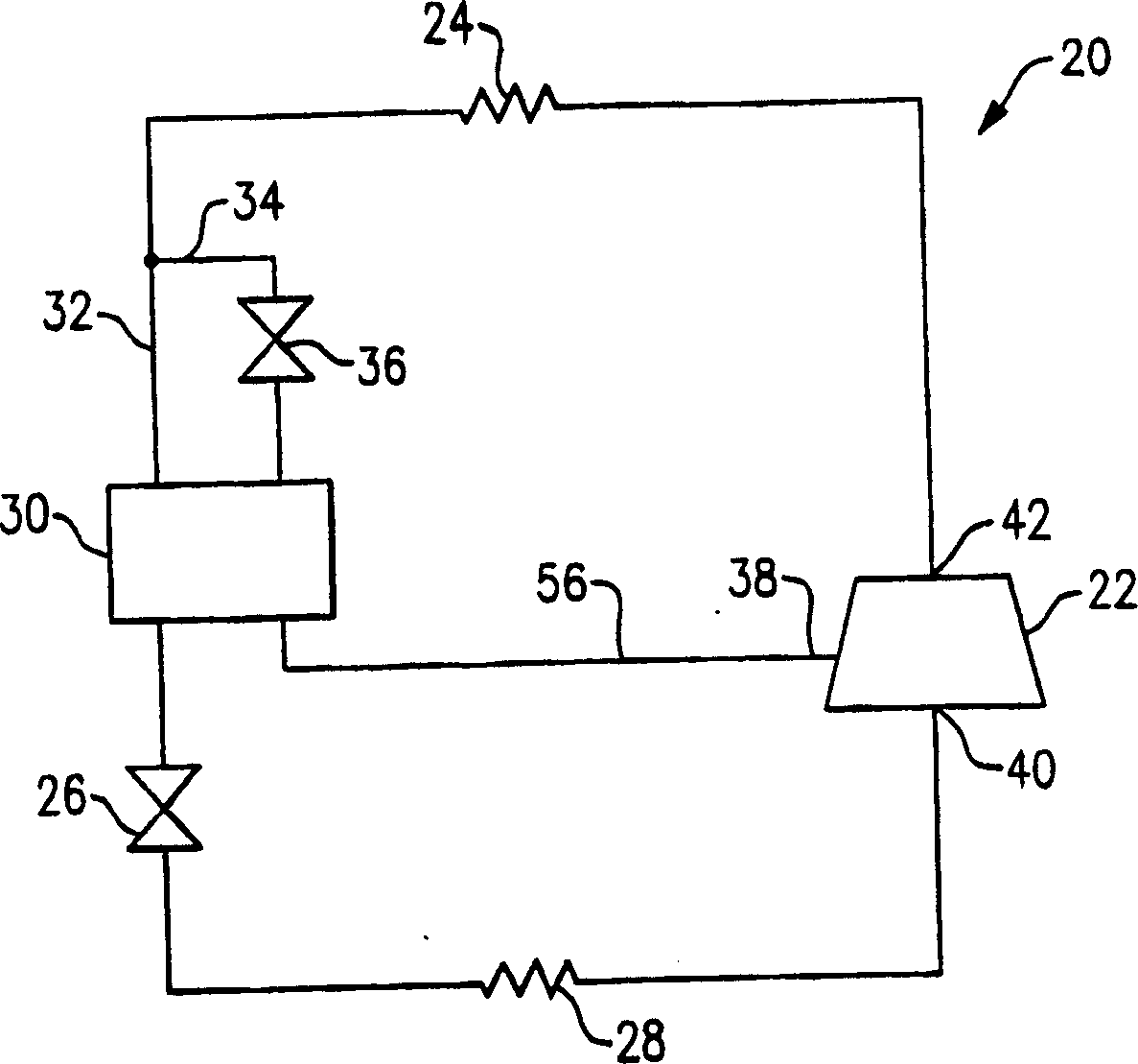
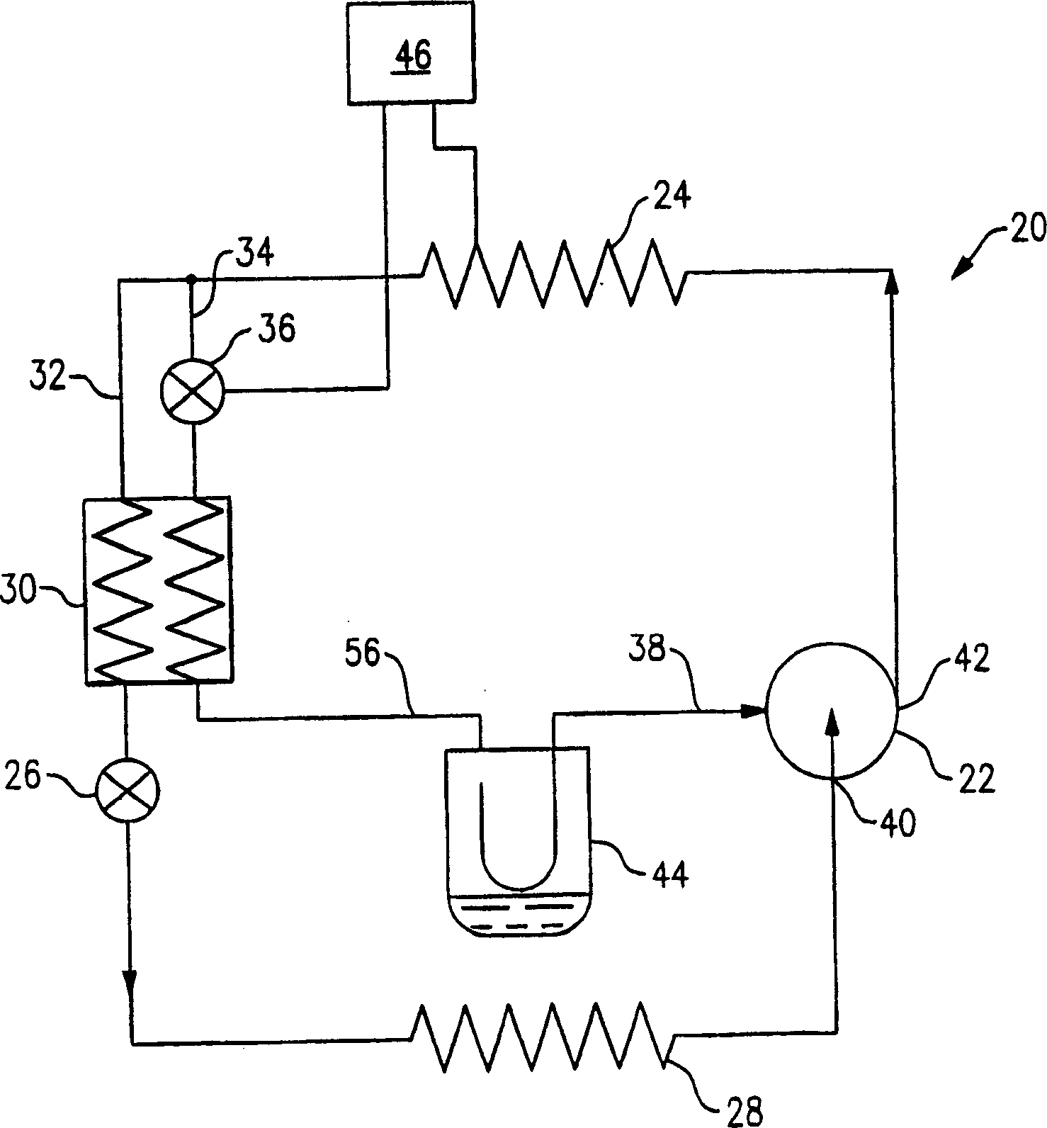
[0013] FIG. 1 schematically shows a prior art refrigeration system 20 . The system 20 includes a compressor 22, a heat sink heat exchanger (gas cooler as a subcritical cycle) 24, a primary expansion device 26, and a heat sink heat exchanger (evaporator) 28, and an economizer heat exchanger 30 . The refrigerant circulates through the circulation system 20 in a closed loop. The refrigerant exits compressor 22 through discharge port 42 at high pressure and high enthalpy. The refrigerant flows through the gas cooler 24 and the refrigerant loses heat to exit with low enthalpy and high pressure. The refrigerant then splits into two flow paths 32 and 34 . The refrigerant in the economizer flow path 34 expands to a low pressure in the economizer expansion device 36 and exchanges heat with the refrigerant in the main flow path 32 located in the economizer heat exchanger 30 to cool the refrigerant in the main flow path. Refrigerant in 32. Refrigerant in the economizer flow path 34 ...


PUM


Abstract

Refrigerant is circulated through an economized refrigeration system including a compressor (22), a gas cooler (24), a main expansion device (26), an economizer heat exchanger (30) and an evaporator (28). After cooling, the refrigerant splits into an economizer flow path (34) and a main flow path (32). Refrigerant in the economizer flow path (34) is expanded to a low pressure and exchanges heat with the refrigerant in the main flow path in the economizer heat exchanger (30). The refrigerant in the main flow path (32) is then expanded and heated in the evaporator (28) and enters the compressor (22), completing the cycle. An accumulator (44) positioned between the economizer heat exchanger (30) and the compressor (22) stores excess refrigerant in the system, regulating the amount of refrigerant in the system and the high pressure in the system. The amount of refrigerant in the accumulator (44) is controlled by regulating the economizer expansion device (36). By adjusting the amount of refrigerant in the accumulator (44), the amount of refrigerant in the system, and therefore the high pressure of the system, can be regulated.

Description

technical field [0001] The present invention generally relates to a system for controlling the high-pressure component of an economizer refrigeration system for controlling the refrigerant in the high-pressure component of the system by means of an interstage collector located between an economizer heat exchanger and a compressor amount. Background technique [0002] Chlorine-containing refrigerants are gradually being phased out due to their potential to destroy ozone. Hydrocarbons (HFCs) have been used as alternative refrigerants, but these refrigerants still have the potential to increase global warming. The use of "natural" refrigerants such as carbon dioxide and propane has also been proposed as an alternative fluid. Unfortunately, the vast majority of these fluids are problematic to use. Carbon dioxide has a low critical point, which allows air conditioning systems using carbon dioxide to actually operate above the critical point, or in most cases supercritical. Th...

Claims


Application Information

Patent Timeline
Patent Type & Authority Applications(China)
IPC IPC(8): F25B9/00F25B43/00
CPCF25B2400/13F25B2600/17F25B2700/19F25B2600/2509F25B2600/2501F25B2309/061F25B43/006F25B2400/16F25B1/10F25B9/008F25B9/00F25B1/00F25B43/00
Inventor T·H·西内尔
Owner CARRIER CORP
Why Eureka
Try Eureka