

Pressure sensor
A pressure sensor and pressure technology, applied in the direction of measuring fluid pressure, instruments, measuring devices, etc., can solve the problems that the signal of the pressure value contains noise, the output of the substrate J6 is unstable, etc.
- Summary
- Abstract
- Description
- Claims
- Application Information
AI Technical Summary
Problems solved by technology
Method used
Image

Examples
no. 1 example
[0040] Hereinafter, a first embodiment of the present invention will be described with reference to the corresponding drawings. The pressure sensor described in this embodiment is used in places where the pressure sensor is subjected to vibrations of several KHz, such as in an engine room of a vehicle and the like.
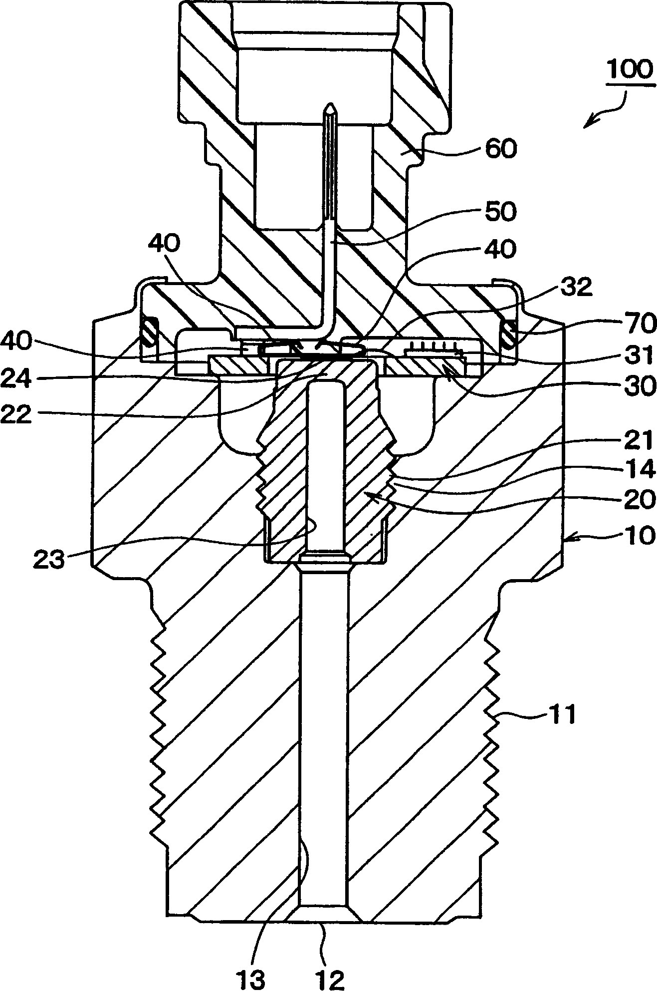
[0041] figure 1 is a schematic cross-sectional view of the pressure sensor 100 in the first embodiment. As shown, the pressure sensor 100 is configured to include a housing 10 , a stem 20 , a substrate 30 , a spring terminal 40 , a terminal 50 , and a connector cover 60 .
[0042] The housing 10 is a hollow housing made of metal and processed by cutting, cold forging or the like, and has a threaded portion 11 which can be connected to a body to be measured by screw fitting. The threaded portion 11 is formed on an outer circumferential surface of one end of the housing 10 . A hole extends from an opening 12 formed at one end of the case 10 to the other end of t...
no. 2 example
[0061] In this embodiment, only the parts different from the first embodiment will be described. This embodiment differs from the first embodiment in that the spring terminal 40 is bonded to the terminal 50 .
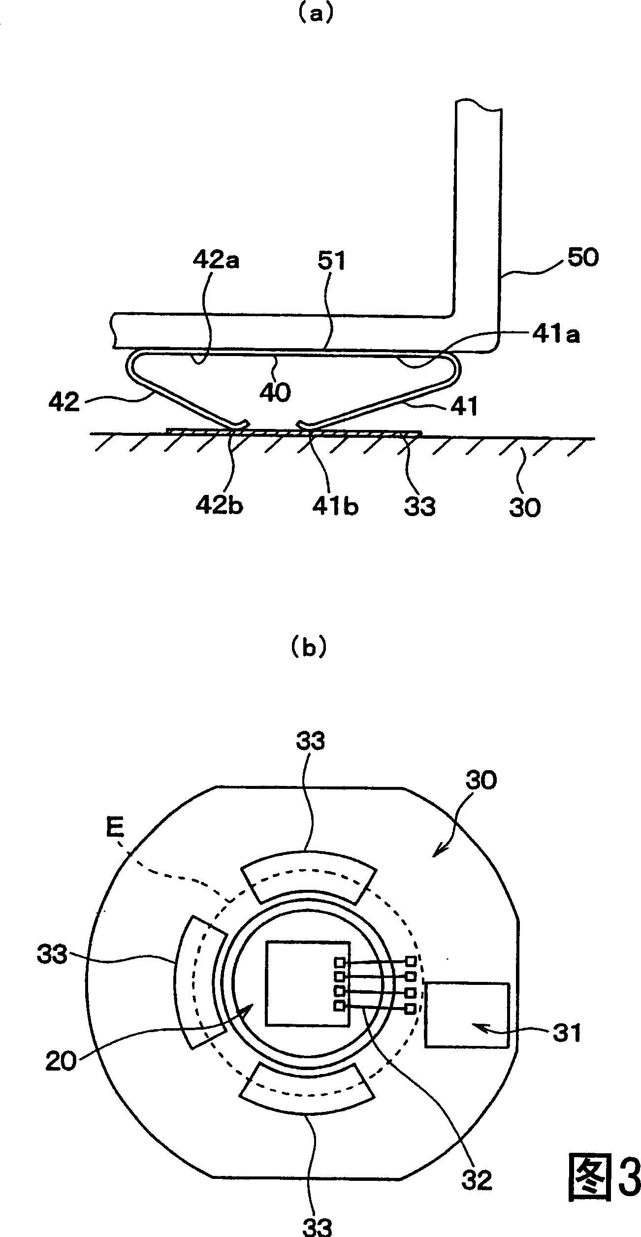
[0062] Fig. 3 is the schematic diagram of spring terminal 40 in this embodiment, wherein Fig. 3 (a) is the schematic diagram of the surrounding area of spring terminal 40, Fig. 3 (b) is the view of substrate 30 when seeing from connector contact 60 side .
[0063] As shown in FIG. 3( a ), the spring terminal 40 is in a state of being adhered to the bottom 51 of the terminal 50 . The spring terminal 40 is glued to the bottom of the terminal 50, for example by resistance welding. Here, for the spring terminal 40 used in this embodiment, the same parts as those in the first embodiment are employed.
[0064] Further, as shown in FIG. 3( b ), the substrate 30 has the electrodes 33 arranged thereon in such a manner that the electrodes 33 are electrically connected to the...
no. 3 example
[0070] In this embodiment, only the parts different from the first and second embodiments are described. In the first and second embodiments described above, the spring terminal 40 in which the natural frequency of each spring portion is different is used. However, in this embodiment, spring terminals are used whose respective spring parts have the same natural frequency, and the arrangement state of the spring terminals is changed, so that the frequencies at which the respective spring parts resonate with external vibrations are set to be different from each other. . Afterwards, will refer to Figure 4 Be explained.
[0071] Figure 4 is a schematic diagram of the surrounding portion of the spring terminal 43 according to the present embodiment. First, in this embodiment, the spring terminal 43 is made of a single metal plate and has a structure in which both sides of the metal plate are bent to form a plurality of two spring portions 43a, 43b. Furthermore, the bent port...
PUM
| Property | Measurement | Unit |
|---|---|---|
| Thickness | aaaaa | aaaaa |
| Width | aaaaa | aaaaa |
Abstract
Description
Claims
Application Information