Round section tubing slitting mill

A circular cross-section, rolling cutting machine technology, applied in the direction of pipe shearing device, shearing device, shearing machine equipment, etc., can solve the problems of inability to realize automatic retraction movement, complex transmission system, and inability to work continuously, and achieve the goal of transmission mechanism Simple and reliable, increase cutting speed, use flexible effects

Inactive Publication Date: 2006-07-26
刘庆国
View PDF0 Cites 11 Cited by
  • Summary
  • Abstract
  • Description
  • Claims
  • Application Information

AI Technical Summary

Problems solved by technology

On the one hand, the discontinuous cam block is used to realize the radial feed of the hob; since there is a complete circular cam, it cannot work continuously
On the other hand, the reverse rotation of the gear mechanism can be controlled by the one-way clutch on the drive shaf

Method used


Image

  • Round section tubing slitting mill
  • Round section tubing slitting mill

Examples


Embodiment Construction

[0016] The present invention will be further described in detail below with reference to the accompanying drawings and embodiments.

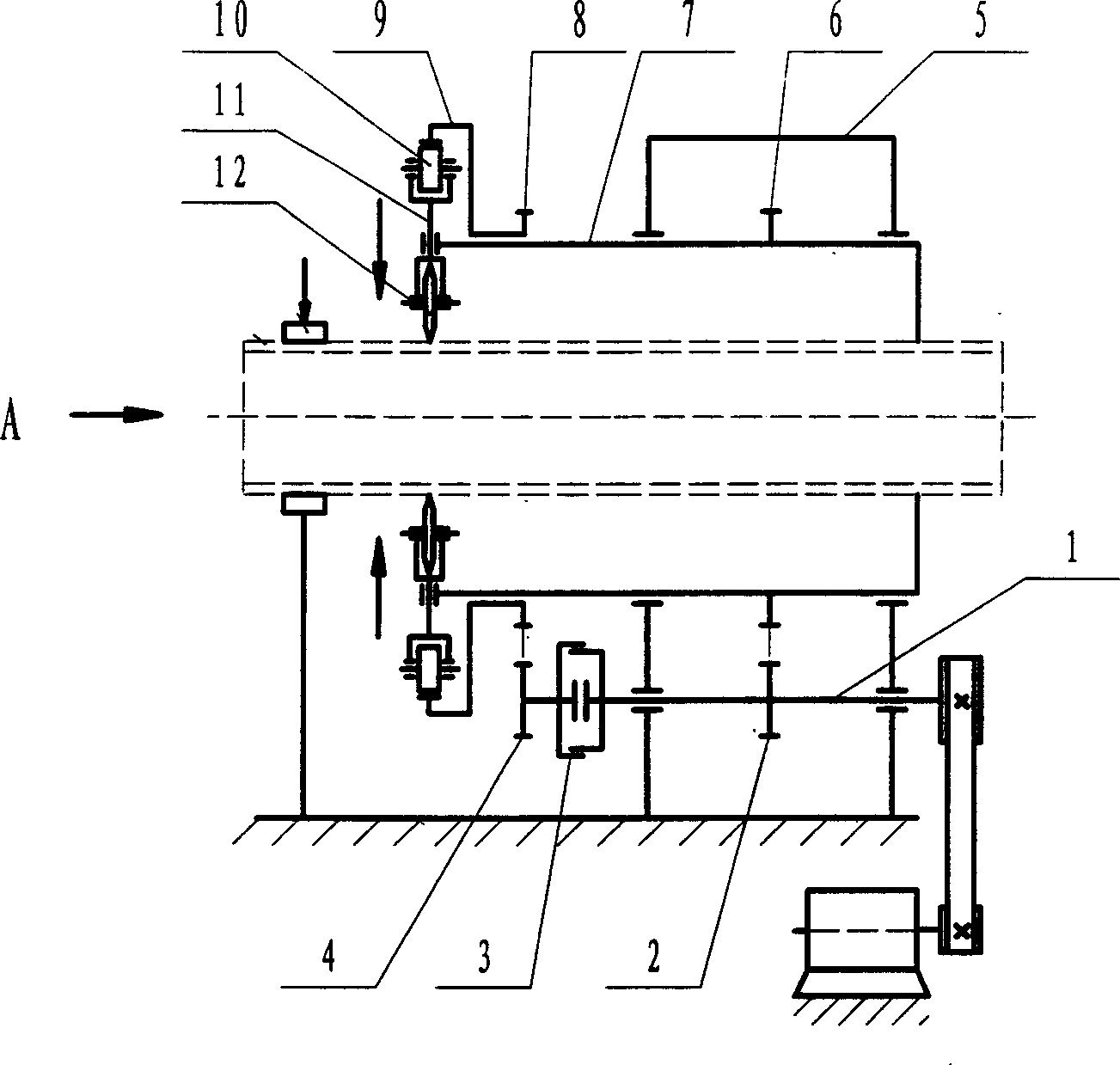
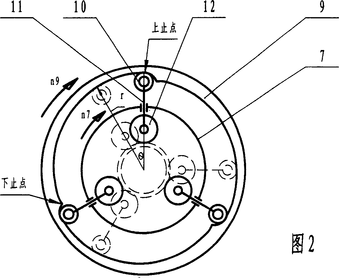
[0017] Depend on figure 1 The shown circular section pipe hobbing machine has a rotating cylinder 7 mounted on the frame 9 through bearings. A rotating ring 9 rotating with it is installed at the leading end of the rotating cylinder 7 . On the inner ring of the rotating ring 9 there is an inner cam formed by connecting Archimedes spiral segments with each other. The end-to-end connection of each segment is a transition connection end with different curvature radii. The rotating cylinder 7 is provided with a hobbing device. The hobbing and cutting device comprises a knife rest slider 11, the upper and lower ends of which are respectively provided with hinged rollers 10 and hinged disc cutters 12, and are movably mounted on the rotating cylinder 7 through the knife rest slider 11. Gears 6 and 8 are respectively provided on the rotating cylinder ...


PUM


Abstract

The invention discloses round section tubes slitting mill, comprising drive axle, drive mechanism comprising rotating cylinder and driving medium, and cylinder cutting mechanism installed on the radial rotating cylinder. The inner ring of rotating cylinder is inner cam which is composed by many curved line; the driving device controlled unit which is composed by driving medium and clutch is installed on the drive axle to control cylinder cutter. The unit possesses the advantages of simple structure and continuous work. The unit is suit for producing tubes production line.

Description

technical field [0001] The invention relates to a pipe cutting device, in particular to a circular section pipe rolling cutting machine which uses a disc knife to roll cut metal pipes. Background technique [0002] At present, for processing and cutting metal pipes, or cutting pipes on the pipe production line, the feed of the hob is hydraulic. That is, the hydraulic cylinder is used to drive, and the radial feed of the hob is realized through the rack mechanism, thus meeting the requirements for pipe cutting. But the most critical problem is that if the hydraulic cylinder is used to push the moving ring through the fork, it is easy to produce partial cutting, and it is difficult to ensure the synchronization of radial feeding; in addition, its overall structure is slightly complicated, and a hydraulic system needs to be configured , and its high maintenance cost. In order to solve this problem, another disclosed metal pipe cutting machine adopts a mechanical feeding metho...

Claims


Application Information

Patent Timeline
IPC IPC(8): B23D21/04
Inventor 刘庆国
Owner 刘庆国
Why Eureka
Try Eureka