
Printer

A technology for printers and print heads, applied in printing devices, printing, transfer materials, etc., can solve the problems of difficult processing, increased cost of ribbon guides, and high prices of materials with high wear resistance

Inactive Publication Date: 2006-07-26
OKI ELECTRIC IND CO LTD
View PDF1 Cites 4 Cited by
  • Summary
  • Abstract
  • Description
  • Claims
  • Application Information

AI Technical Summary

Problems solved by technology

However, materials with high wear resistance are expensive and difficult to process
Therefore, the cost of the ribbon guide is increased, and thus the cost of the printer is also increased

Method used


Image

  • Printer
  • Printer
  • Printer

Examples


Embodiment Construction

[0021] Hereinafter, embodiments of the present invention will be described in detail with reference to the drawings.

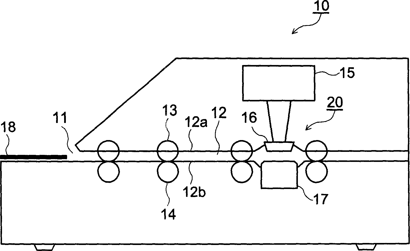
[0022] figure 2 is a schematic diagram of a printer according to an embodiment of the present invention.

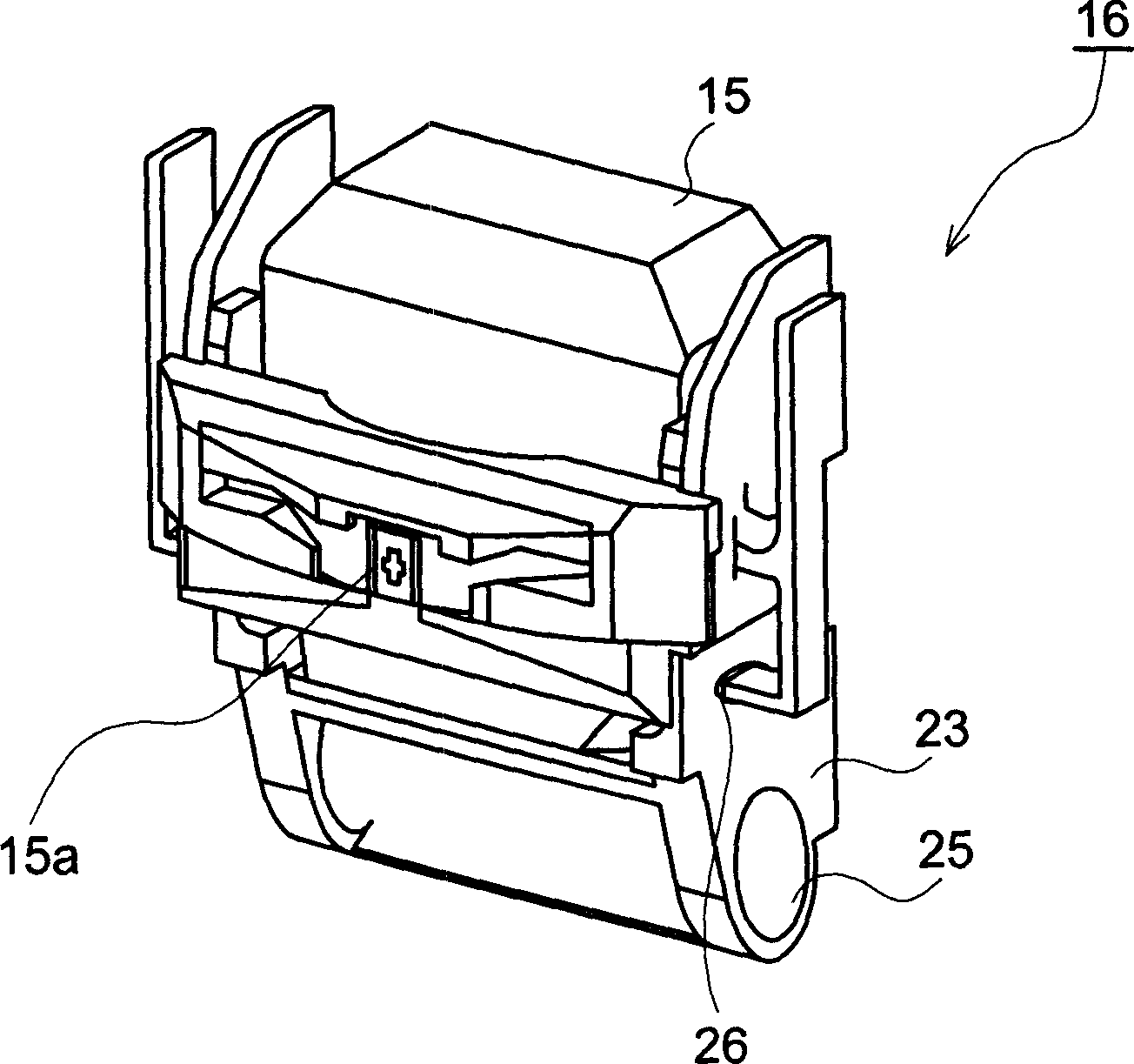
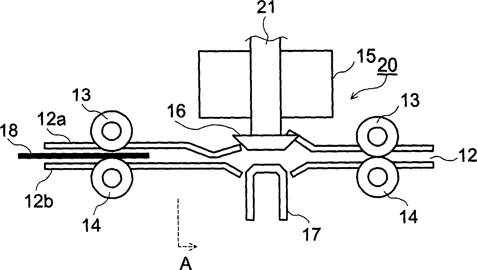
[0023] In the figure, 10 is a printer, which has: a print medium insertion port 11 for inserting a print medium 18, a print medium conveyance path 12 for conveying the print medium 18, and a plurality of conveyance channels along the print medium conveyance path 12. The roller 13 and the pressure roller 14, the printing head 15 arranged in the printing section 20 in the middle of the above-mentioned printing medium conveying path 12, the ribbon guide 16 installed on the carriage 23 described later, and the printing section 20 is equipped with a printing platen 17. Here, the printer 10 is a voucher accounting machine or the like used in financial institutions such as banks, post offices, and credit unions (financial cooperatives in Japan) to write vouch...


PUM


Abstract

The printer comprises a carriage 23 moving in the direction perpendicular to the carrying direction of a medium, a print head 15 mounted on the carriage 23 and printing on the medium, and a ribbon guide 16 for guiding the ink ribbon to the forward end face of the print head 15. The ribbon guide 16 has a medium guide surface abutting against the medium and engages removably with the carriage 23 or the print head 15. Thus, the printer in which a ribbon guide can engage removably with a print head or a carriage mounting the print head and an ink ribbon can be replaced easily, surface of the ink ribbon abutting against a medium is prevented from abrading significantly to vary the interval between the upper surface of the medium and the print head, print quality is prevented from deteriorating, and winding of the ink ribbon is carried out with no trouble.

Description

technical field [0001] The present invention relates to printers. Background technique [0002] Conventionally, in financial institutions such as banks, post offices, and credit unions (financial cooperatives in Japan), printers such as voucher bookkeeping machines have been used to record accounts on vouchers such as deposit books (for example, refer to Patent Document 1). In this printer, in order to print accounting at the specified position of the printing medium of voucher or document, the printing medium inserted into the voucher accounting machine from the insertion port is conveyed to the printing medium by rollers such as conveying rollers arranged on the conveying path. department. [0003] Here, the printing unit has: a print head, a printing platen facing the print head across a delivery path, and a ribbon guide (ribbon) for guiding the ribbon to move along the front end of the print head. guide). Additionally, the ribbon guide is mounted on the printhead. On...

Claims


Application Information

Patent Timeline
IPC IPC(8): B41J35/04B41J11/62B41J17/32
CPCB41J17/32B41J35/04B41J35/12
Inventor 大山刚司久下英七池田恭之
Owner OKI ELECTRIC IND CO LTD
Learn More