Dry gas sealer for compressor with low inlet pressure and liquid-carrying medium

A technology of inlet pressure and gas sealing, which is applied in the sealing of engines, liquid variable displacement machines, mechanical equipment, etc., can solve the problems of easy liquid, low compressor inlet temperature, and seal damage, so as to prevent accumulation and improve reliability sex, to avoid the effect of liquid

Inactive Publication Date: 2006-08-02
JOHN CRANE TECH TIANJIN
View PDF0 Cites 4 Cited by
  • Summary
  • Abstract
  • Description
  • Claims
  • Application Information

AI Technical Summary

Problems solved by technology

However, the sealing device of this structure also has some shortcomings: for the case where the inlet temperature of the compressor is low and the dew point temperature of the working medium is high, the main sealing gas is easy to carry liquid after throttling and cooling, such as ammonia gas, because the gas can only pass through The leakage of the sealing surface flows to the inside and outside, and the flow rate is very small, which will cause liquid in the air intake chamber B and the first-stage sealing surface, which will cause the seal to run unstable, and the leakage will fluctuate greatly, and even cause damage to the seal

Method used


Image

  • Dry gas sealer for compressor with low inlet pressure and liquid-carrying medium
  • Dry gas sealer for compressor with low inlet pressure and liquid-carrying medium
  • Dry gas sealer for compressor with low inlet pressure and liquid-carrying medium

Examples


Embodiment 1

[0030] Example 1: Please refer to image 3 .

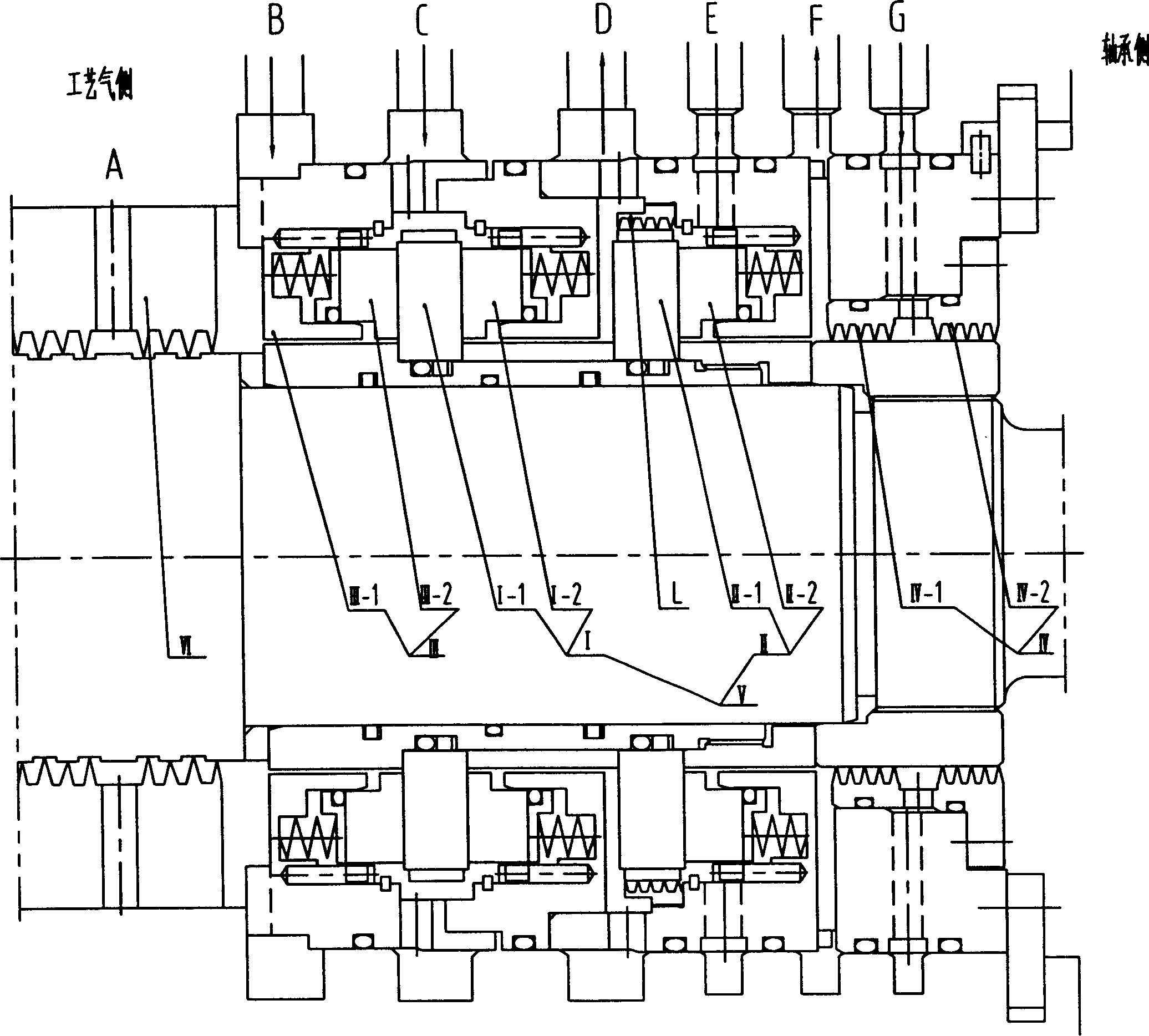
[0031] This example is in figure 1 It is realized on the basis of the known technology shown, that is, the first-stage end face seal I composed of the moving ring I-1 and the static ring I-2 is provided, and the second-stage end face is composed of the moving ring II-1 and the static ring II-2. Seal II, they together form a two-stage serial end face seal V, and a single end face seal III composed of a spring seat III-1 and a static ring III-2 is installed before the first stage end face seal, between the first stage end face seal and the second stage There is a labyrinth seal L between the two-stage end face seals, and a rear isolation seal IV is connected behind the two-stage series end face seals, and IV-1 and IV-2 respectively represent the labyrinth of the rear isolation seal (rear labyrinth) The improvement lies in the fact that the front end of the spring seat III-1 with a single end face seal installed before the first st...

Embodiment 2

[0032] Example 2: Please refer to Figure 4 .

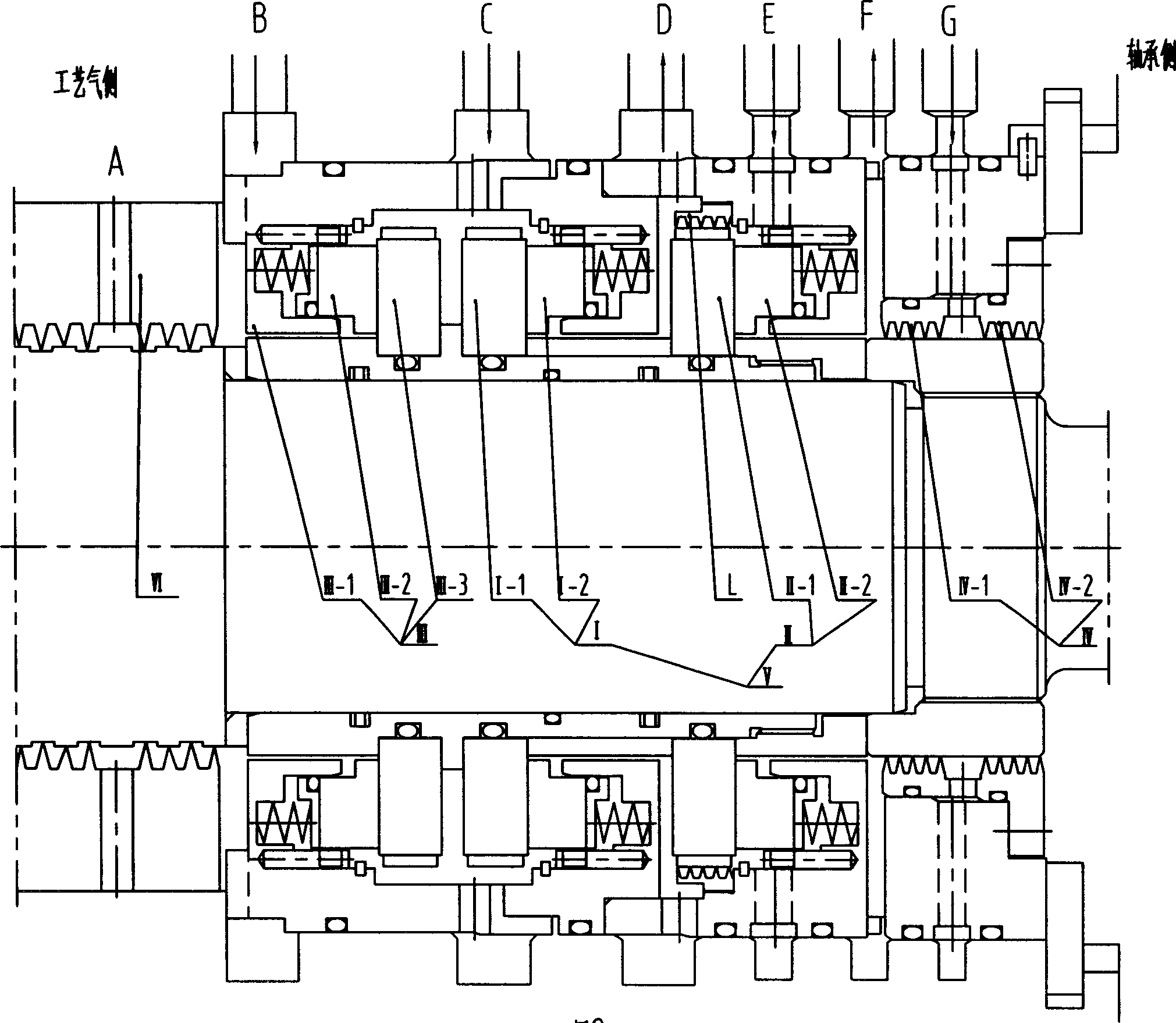
[0033] This example is in figure 2 It is realized on the basis of the known technology shown, and the difference between the known part of its structure and the first embodiment is that a Moving ring III-3, the improved part related to the content of the present invention is completely the same as that of the first embodiment.

Embodiment 3

[0034] Example 3: Please refer to Figure 5 and Figure 7 .

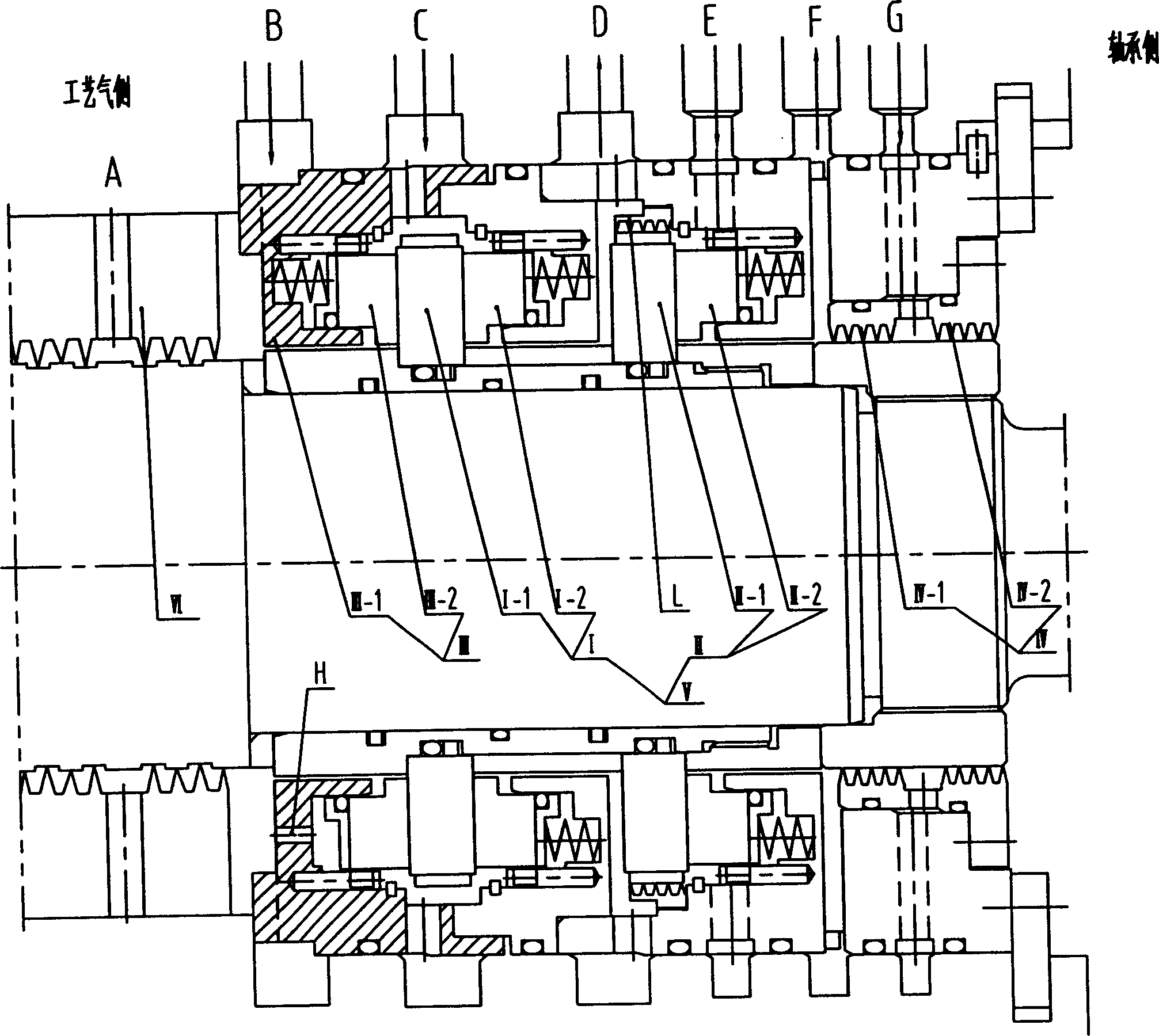
[0035] This example is in figure 1 Realized on the basis of the known technology shown, the known part of its structure is exactly the same as that described in Embodiment 1, and its improvement is that the outer threaded connection of the spring seat III-1 is as follows Figure 7 Shown consists of a housing 1 with an air inlet, a spherical valve flap 3 installed at the air inlet of the inner cavity of the housing, a screw plug 4 with an air outlet that is threaded at the front end of the housing, and a screw plug 4 installed in the inner cavity of the housing. The miniature one-way valve formed by the spring 2 connected between the spherical disc and the plug, has an air inlet hole leading to the air inlet of the miniature one-way valve housing on the inner side of the spring seat, and the miniature one-way valve The number of valves can be determined according to specific application requirements. This type of ...


PUM


Abstract

The dry gas sealer for compressor consists of mainly two-stage serial end sealing comprising the first end sealing and the second end sealing, the single end sealing before the first end sealing, the labyrinthian sealing between the first end sealing and the second end sealing, and the post isolating sealing, and features the ventilating mechanism set on the spring seat of single end sealing and leading to the pre-buffering gas intake cavity in the structure of small hole and/or non-return valve. The present invention has the features of increased main sealing gas flow rate to avoid gas carrying of the main sealing gas, the timely release of the micro liquid drop in the main sealing gas to avoid collection and the reliable running of the sealer.

Description

technical field [0001] The invention belongs to a sealing device for a rotating shaft in a fluid machine, in particular to a dry-type gas sealing device for a compressor used for a medium with low inlet pressure and which is easy to carry liquid. Background technique [0002] There are many types of dry gas seals used in the current known compressors of various types, and also at the ends of the rotating shafts of fluid machines such as expanders, separators, pumps, and reactor agitators. See figure 1 and figure 2 , figure 1 and figure 2 Shown is a kind of dry gas sealing device mentioned in Chinese patent ZL2003201119176 (the difference is: figure 2 A moving ring III-3) is added to the first-stage end face seal of the first stage. Its working principle is: the buffer gas (generally the process gas from the compressor outlet) that has been purified by filtration enters the pre-buffer gas inlet cavity B, its pressure P B It should be higher than the pressure P of the...

Claims


Application Information

Patent Timeline
Patent Type & Authority Applications(China)
IPC IPC(8): F04B39/00F16J15/16
Inventor 杨惠霞王玉明冯向忠张瑞祥杨明王海宁
Owner JOHN CRANE TECH TIANJIN
Why Eureka
Try Eureka