
Backlight assembly, method of manufacturing the same and liquid crystal display apparatus having the same

A technology of backlight components and optical components, applied in optics, electrical components, nonlinear optics, etc., can solve the problems of increasing the thickness of backlight components and increasing the light loss of LCD devices, etc., and achieve the effect of thickness reduction and brightness increase

Inactive Publication Date: 2006-08-02
SAMSUNG ELECTRONICS CO LTD
View PDF0 Cites 3 Cited by
  • Summary
  • Abstract
  • Description
  • Claims
  • Application Information

AI Technical Summary

Problems solved by technology

As a result, the light loss of the LCD device is increased, and the thickness of the backlight assembly is destructively increased

Method used


Image

  • Backlight assembly, method of manufacturing the same and liquid crystal display apparatus having the same
  • Backlight assembly, method of manufacturing the same and liquid crystal display apparatus having the same
  • Backlight assembly, method of manufacturing the same and liquid crystal display apparatus having the same

Examples


Embodiment Construction

[0026] Hereinafter, the present invention will be described more fully with reference to the accompanying drawings. In the drawings, the thickness of coatings, films and regions are exaggerated for clarity. Like reference numerals refer to like elements throughout. It will be understood that when an element such as a coating, film, region, or substrate is referred to as being "on" another element, it can be directly on the other element or intervening elements may also be present.

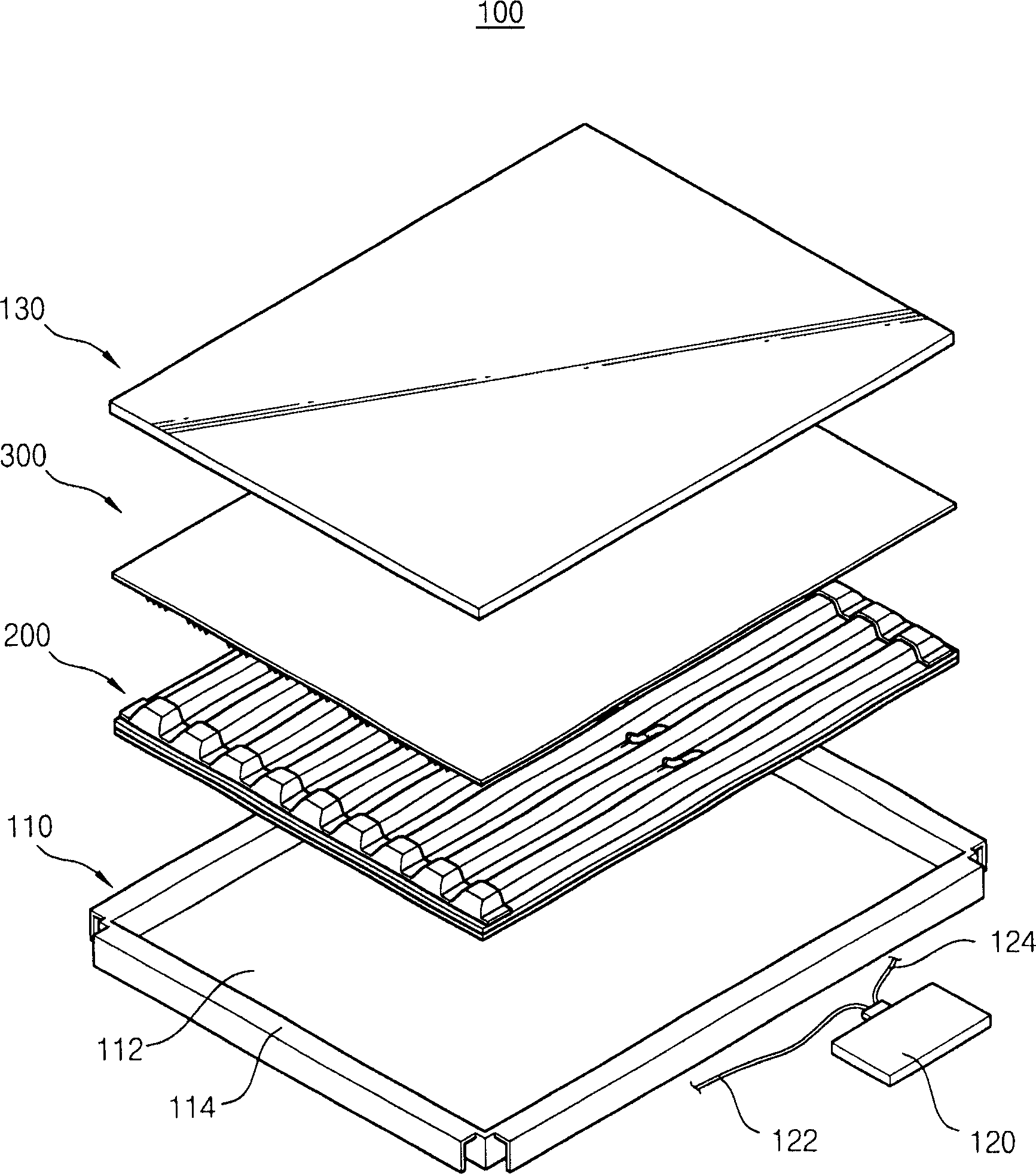
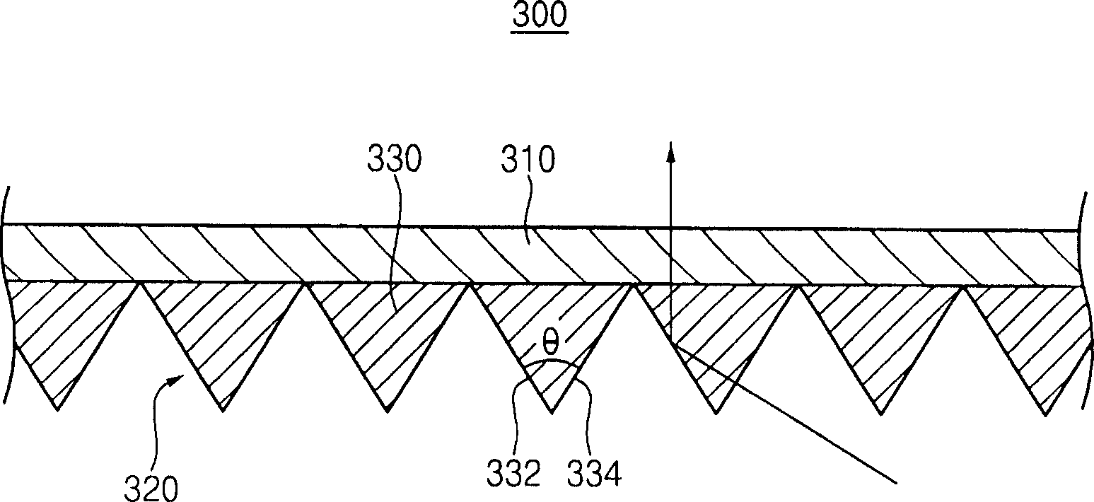
[0027] figure 1 is an exploded perspective view showing a typical embodiment of a backlight assembly according to the present invention. figure 2 is showing figure 1 A cross-sectional view of a typical flat fluorescent lamp, typical optical components, and a typical diffuser plate;

[0028] refer to figure 1 and 2 , the backlight assembly 100 includes a receiving container 110 , a flat fluorescent lamp 200 , an optical part 300 , and an inverter 120 .

[0029] The receiving container 110 in...


PUM


Abstract

A backlight assembly includes a receiving container having a receiving space, a flat-type light source, an optical member, and an inverter. The flat-type light source has a plurality of light emitting spaces spaced apart from each other and is received into the receiving space. The optical member has a prism pattern formed in areas corresponding to areas between adjacent light emitting spaces and disposed at a light emitting direction of the flat-type light source. The inverter generates a voltage for the flat-type light source. The prism pattern 1o includes prisms having a substantially trigonal prism and continuously connected one after another. Thus, the backlight assembly may improve brightness uniformity thereof and have a reduced thickness.

Description

technical field [0001] This application claims priority from Korean Patent Application No. 2005-6579 filed on Jan. 25, 2005, the entire contents of which are hereby incorporated by reference. Background technique [0002] The invention relates to a backlight assembly, a manufacturing method of the backlight assembly, and a liquid crystal display (LCD) device with the backlight assembly. More particularly, the present invention relates to a backlight assembly with increased brightness and reduced thickness, a manufacturing method of the backlight assembly, and an LCD device having the same. Background technique [0003] In general, a liquid crystal display (LCD) device displays images using electro-optical characteristics of liquid crystals, such as anisotropic refractive index and anisotropic dielectric constant. Compared with other display devices such as cathode ray tubes (CRTs) and plasma display panels (PDPs), LCD devices have features such as light weight, low power ...

Claims


Application Information

Patent Timeline
Patent Type & Authority Applications(China)
IPC IPC(8): G02F1/13357G02F1/133G02B5/04G02F1/1335
CPCG02F1/133604H01J61/305H01J65/046G02F2001/133607G02F1/133611G02F1/133607G02F1/1335
Inventor 姜硕桓朴惠恩李相裕黄仁瑄金重玄
Owner SAMSUNG ELECTRONICS CO LTD
Learn More