Joint torque sensor capable eliminating harmonic wave effect by itself

A joint torque and harmonic elimination technology, applied in the field of joint torque sensors, can solve the problem that the joint torque sensor cannot eliminate the influence of harmonics

Inactive Publication Date: 2006-08-09
HARBIN INST OF TECH
View PDF0 Cites 16 Cited by
  • Summary
  • Abstract
  • Description
  • Claims
  • Application Information

AI Technical Summary

Problems solved by technology

[0003] In order to solve the problem that the existing joint torque sensor cannot eliminate the influence of harmonics, the present invention provides a joint torque sensor that can eliminate the influence of harmonics itself, and the torque sensor itself can compensate the influence of harmonics generated by the harmonic reducer

Method used


Image

  • Joint torque sensor capable eliminating harmonic wave effect by itself
  • Joint torque sensor capable eliminating harmonic wave effect by itself
  • Joint torque sensor capable eliminating harmonic wave effect by itself

Examples


specific Embodiment approach 1

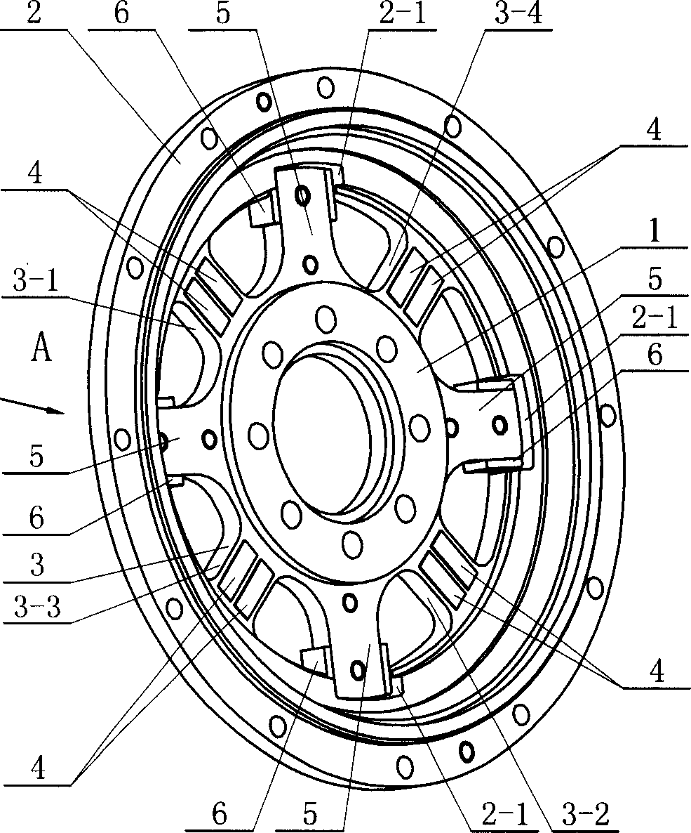
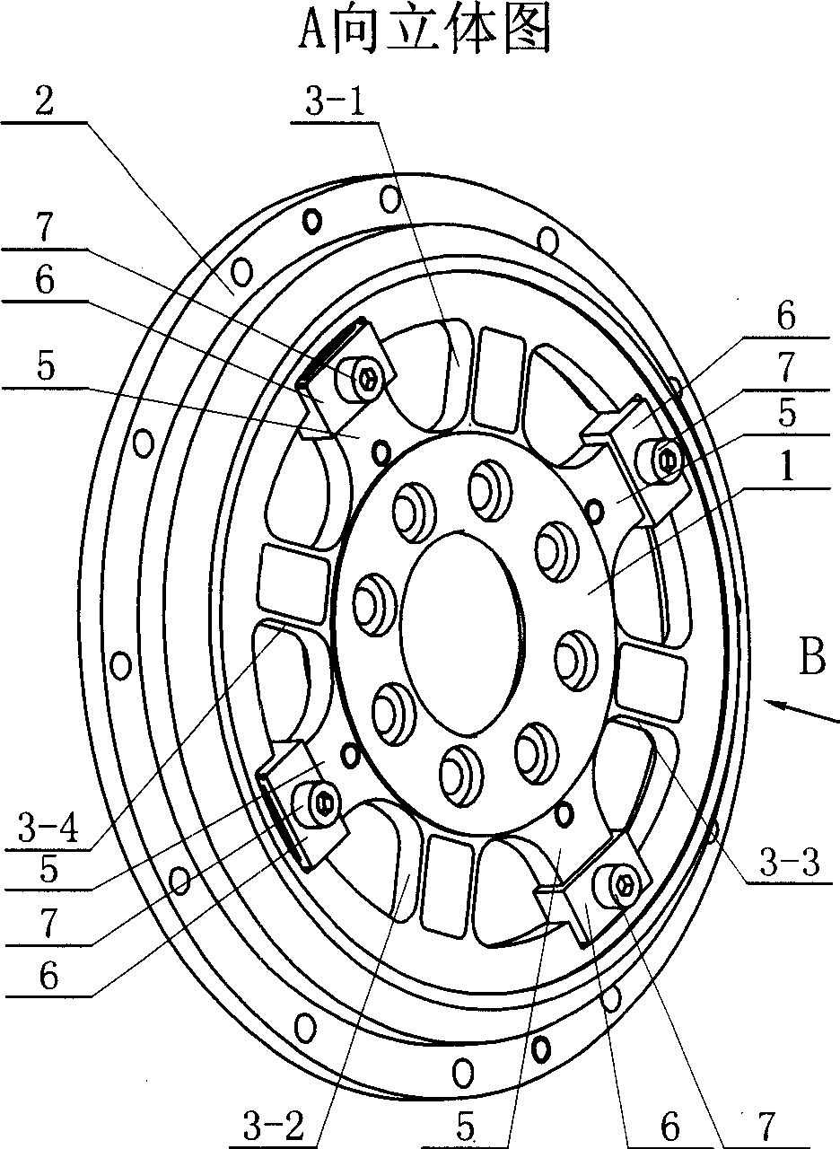
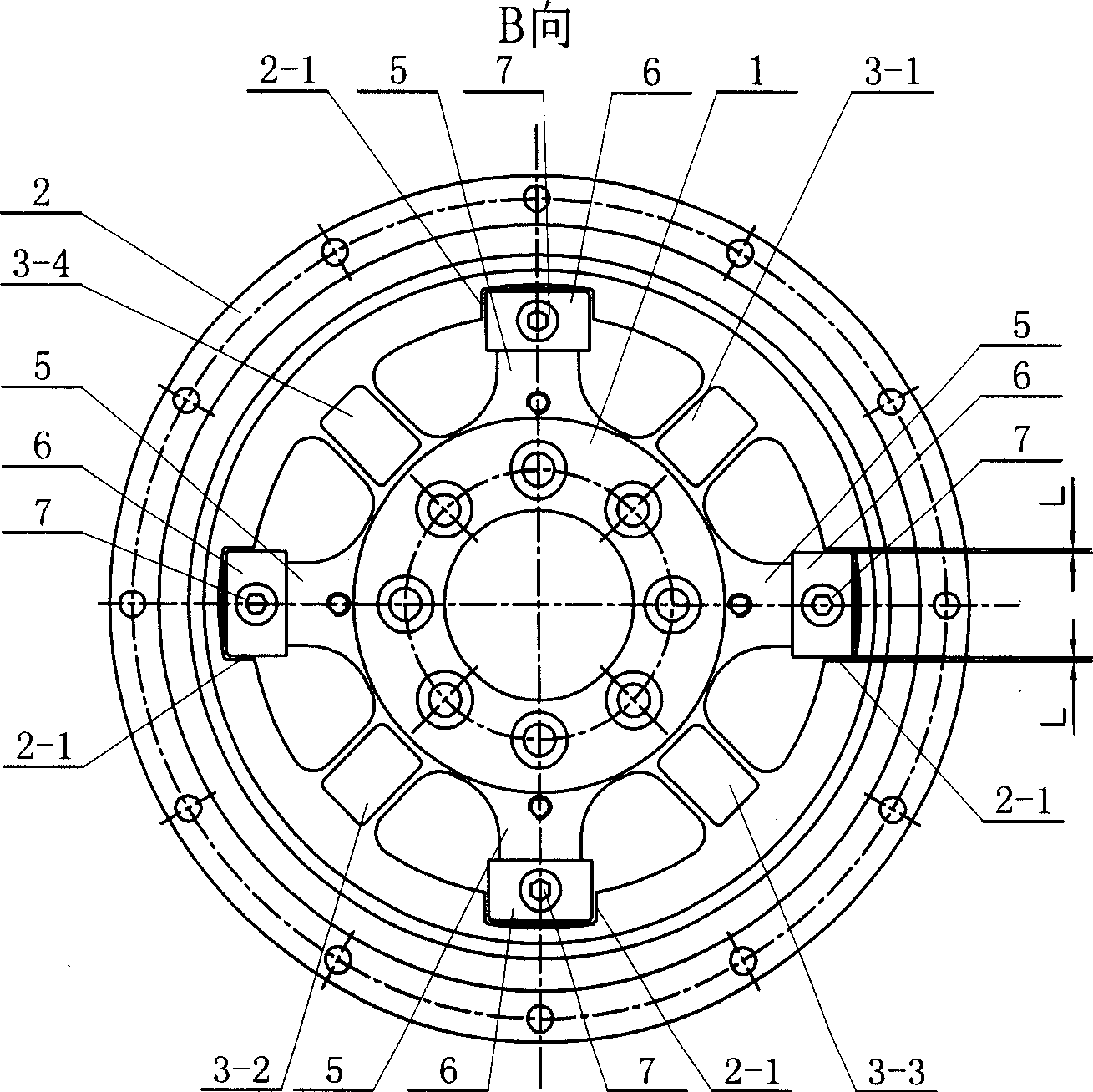
[0005] Specific implementation mode one: (see Figure 1-Figure 4 ) This embodiment includes a torque input disc 1, a torque output disc 2, a sensor strain beam 3 and a strain gauge 4, and there are four sensor strain beams 3, which are No. 1 strain beam 3-1, No. 2 strain beam 3-2, Both ends of No. 3 strain beam 3-3 and No. 4 strain beam 3-4, No. 1 strain beam 3-1, No. 2 strain beam 3-2, No. 3 strain beam 3-3 and No. 4 strain beam 3-4 Respectively connected with the outer edge of the torque input disc 1 and the inner edge of the torque output disc 2 as a whole and uniformly distributed along the circumference of the torque input disc 1; the strain gauges 4 are eight, No. 1 strain beam 3-1, No. 2 strain gages No. strain beam 3-2, No. 3 strain beam 3-3 and No. 4 strain beam 3-4 are respectively fixed with two strain gauges 4, and No. 1 strain beam 3-1 and No. 2 strain beam 3-2 are fixed with four strain gauges. The four strain gauges 4 on the No. 3 strain beam 3-3 and the No. 4 ...

specific Embodiment approach 2

[0006] Specific implementation mode two: (see Figure 1-Figure 3 ) The difference between this embodiment and the specific embodiment one is that the eight strain beams fixed on No. 1 strain beam 3-1, No. 2 strain beam 3-2, No. 3 strain beam 3-3 and No. 4 strain beam The strain gauges 4 are located on the same plane. Other compositions and connections are the same as in the first embodiment. The eight strain gauges 4 described in this embodiment are located on the same plane, and the strain gauges adopt a full-plane pasting method, which is convenient for pasting.

specific Embodiment approach 3

[0007] Specific implementation mode three: (see Figure 1-Figure 3 ) The difference between this embodiment and the specific embodiment 1 or 2 is that it increases the sensor protection beam 5, and the sensor protection beam 5 is fixedly connected with the outer edge of the moment input disc 1 between two adjacent sensor strain beams 3, The inner edge of the torque output disk 2 is provided with a protective beam installation groove 2-1 corresponding to the sensor protection beam 5, and the end of the sensor protection beam 5 is placed in the protective beam installation groove 2-1 on the torque output disk 2. And a gap L is formed between the two side walls of the protection beam installation groove 2-1. Other compositions and connections are the same as those in Embodiment 1 or Embodiment 2. During the working process of the joint, excessive load torque may occur, which will damage the joint torque sensor and make it unable to work normally. The overload protection structur...


PUM


Abstract

Present invention provides joint moment transducer capable of self eliminating harmonic influence. It includes moment inputting disk, moment outputting disk, four transducer straining beams, and eight strain gauges, wherein two ends of four beams integrally connected respectively with moment inputting disk outer edge and inner edge, and rectangular distribution along circumference, each straining beam respectively fixed with two strain gauges, eight strain gauges constituting two holotype full bridge. Said invented two full bridges present quadrature distribution, making output torque carried harmonic mutually counteracted. Said invention can effectively restrain influence to output signal of harmonic speed reducer output pulsation, improving transducer output signal quality raising robot behavioral control precision.

Description

technical field [0001] The invention relates to a joint moment sensor. Background technique [0002] The harmonic reducer has the characteristics of light weight, small size, large reduction ratio, high efficiency, and small return stroke difference. It has been widely used in the drive mechanism of manipulators and robot joints. When the robot hand grasps an object or the robot arm completes a specific action, it uses the feedback signal of the joint torque sensor to achieve precise torque control. However, the existing joint torque sensor cannot eliminate the influence of harmonics. The detected The joint output torque is the joint torque with harmonics, which will interfere with the output signal of the joint torque sensor and reduce the control precision of the system. Contents of the invention [0003] In order to solve the problem that the existing joint torque sensor cannot eliminate the harmonic influence, the present invention provides a joint torque sensor that ...

Claims


Application Information

Patent Timeline
Patent Type & Authority Applications(China)
IPC IPC(8): G01L3/00
Inventor 刘宏史士财高晓辉金明河谢宗武
Owner HARBIN INST OF TECH
Why Eureka
Try Eureka