
Differential termination and attenuator network for a measurement probe

An attenuator and moving terminal technology, which is applied to the parts of electrical measuring instruments, measuring devices, measuring electrical variables, etc., can solve impossible measurement signals, reduce the effective linear dynamic range of the amplifier 34, overexcitation of the differential amplifier 34, etc. question

Inactive Publication Date: 2006-08-09
TEKTRONIX INC
View PDF1 Cites 1 Cited by
  • Summary
  • Abstract
  • Description
  • Claims
  • Application Information

AI Technical Summary

Problems solved by technology

However, any non-zero DC common-mode voltage present at the input of the difference amplifier 34 will reduce the effective linear dynamic range of the amplifier 34
Large DC common-mode voltages in the input signal can easily overdrive the difference amplifier 34, making it impossible to measure the normally small differential mode signal

Method used


Image

  • Differential termination and attenuator network for a measurement probe
  • Differential termination and attenuator network for a measurement probe
  • Differential termination and attenuator network for a measurement probe

Examples


Embodiment Construction

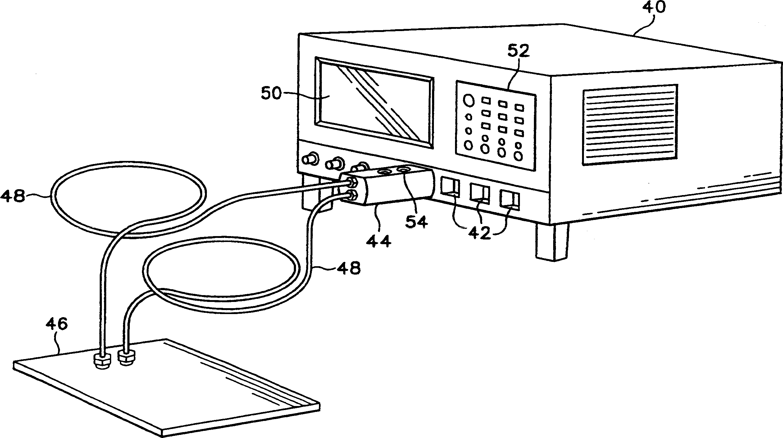
[0017] refer to figure 2 , shows a measurement test instrument 40, such as an oscilloscope TDS6804B manufactured and sold by Tektronix Corporation. The oscilloscope 40 has a plurality of auxiliary interfaces 42 for connecting one or more auxiliary devices 44, such as a differential measurement probe including the input differential termination and attenuator network of the present invention, to the oscilloscope. As described in US Patent 6,629,048B1 titled "Measurement Test Instrument and Associated Voltage Measurement System for Accessory Device", each auxiliary interface 42 has a coaxial signal input line and a voltage source, clock, data, sense, and memory power lines, which are fully incorporated by reference into this application. Auxiliary interface 42 provides a voltage source from oscilloscope 40 to measurement probe 44 and provides two-way communication between oscilloscope 40 and probe 44 . The differential measurement probe 44 is connected to the device under test...


PUM


Abstract

A differential termination and attenuator network receives a differential input signal having a DC common mode voltage. The network circuit includes first and second input termination resistors coupled in parallel with corresponding resistive attenuator circuits. A monitoring circuit coupled to input nodes of the network generates an output signal representative of the combination of a DC common mode voltage on the input nodes and an applied termination voltage. A control circuit receives the output signal from the monitoring circuit and the applied termination voltage and generates a scaled termination voltage and a scaled compensation voltage and drive currents. The scaled termination and compensation voltages and drive currents provide DC currents through the input termination resistances and the attenuators for nulling DC currents at the network input nodes and provides a DC common mode voltage output from the first and second attenuators for optimizing the dynamic range of a differential measurement amplifier.

Description

technical field [0001] The present invention relates generally to differential measurement probes with input signal terminations, and more precisely to differential termination and attenuator networks for measurement probes with DC common-mode voltage compensation. Background technique [0002] High-speed measurement systems typically feature resistive input terminations that match the characteristic impedance of the input signal transmission line. Doing so minimizes problems with input signal reflections and provides the best signal fidelity. A dual 50 ohm input termination network is the most common topology for high speed differential systems. Although the 50 ohm input terminals are usually connected to the measurement system ground, some applications require that the terminals be connected to a common-mode DC terminal voltage. Efficient operation of an adjustable DC termination voltage in the measurement termination network allows control of the DC load of a signal sou...

Claims


Application Information

Patent Timeline
Patent Type & Authority Applications(China)
IPC IPC(8): G01R1/24
CPCG01R1/06766
Inventor I·G·波洛克R·A·范埃普斯
Owner TEKTRONIX INC
Features
  • Generate Ideas
  • Intellectual Property
  • Life Sciences
  • Materials
  • Tech Scout
  • Unparalleled Data Quality
  • Higher Quality Content
  • 60% Fewer Hallucinations
Learn More