Liquid crystal panel module with coated film limiting device

A liquid crystal panel and chip-on-film technology, which is applied in the field of position-limitable chip-on-film, can solve the problems of lowering the product quality rate, affecting the normal function of the chip-on-film 11, and scratching the chip-on-film 11, etc., so as to improve the quality of the products. rate effect

Inactive Publication Date: 2006-08-09
CHUNGHWA PICTURE TUBES LTD
View PDF0 Cites 9 Cited by
  • Summary
  • Abstract
  • Description
  • Claims
  • Application Information

AI Technical Summary

Problems solved by technology

[0003] During the assembly process of the existing LCD module 1, the free end of the chip-on-chip film 11 on the side of the liquid crystal panel 12 that is not connected to the printed circuit board is exposed due to the toughness of its material, after it is hot-pressed and pasted on the liquid crystal panel 12 And suspended on the liquid crystal panel 12, when the iron frame 13 is assembled, the iron frame 13 will be pressed down to combine with the backlight module 14 placed on the stage (not shown) and the liquid crystal panel 12 is placed. , the chip-on-chip film 11 is in contact with the iron frame 13, and is bent downward under force, and is sandwiched between the iron frame 13 and the backlight module 14. When the wall surface where the iron frame 13 contacts the chip-on-chip film 11 forms burrs , it is easy to cause scratches on the chip-on-chip film 11 due to friction, which affects the normal function of the chip-on-chip film 11
[0004] On the other hand, after the LCD module 1 is assembled, the COF 11 is directly in contact with the iron frame 13 without any fixing. When the iron frame 13 is subjected to external vibration or impact, secondary scratches may be caused to the COF 11 Or bending and other bad results, which will affect the normal function of the LCD module 1, resulting in a decrease in the rate of good products

Method used


Image

  • Liquid crystal panel module with coated film limiting device
  • Liquid crystal panel module with coated film limiting device
  • Liquid crystal panel module with coated film limiting device

Examples


Embodiment Construction

[0033] Regarding the foregoing and other technical contents, features, and effects of the present invention, the following detailed descriptions of three preferred embodiments with reference to the accompanying drawings will be more clearly understood.

[0034] Before the present invention is described in detail, it should be noted that in the following description, the same elements are represented by the same numbers.

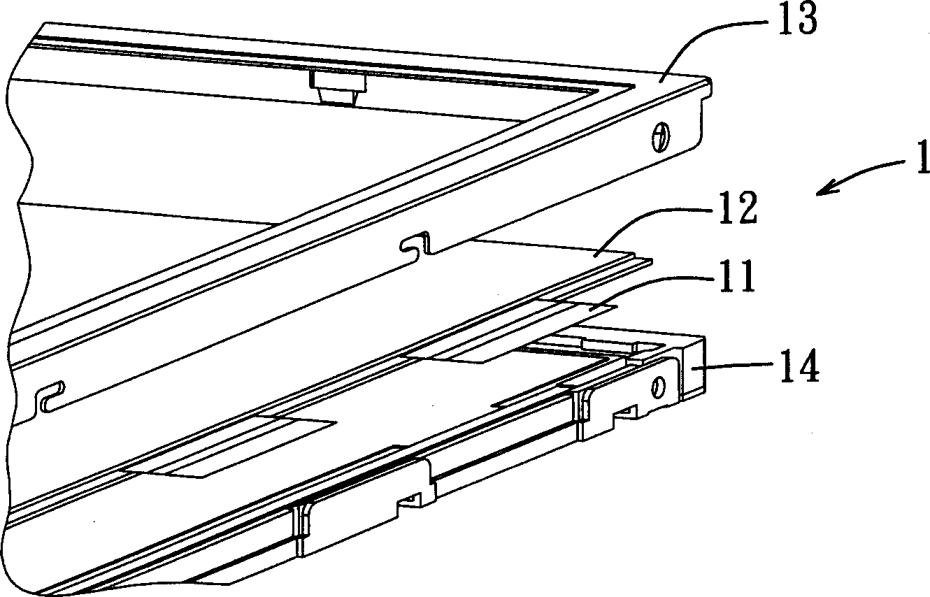
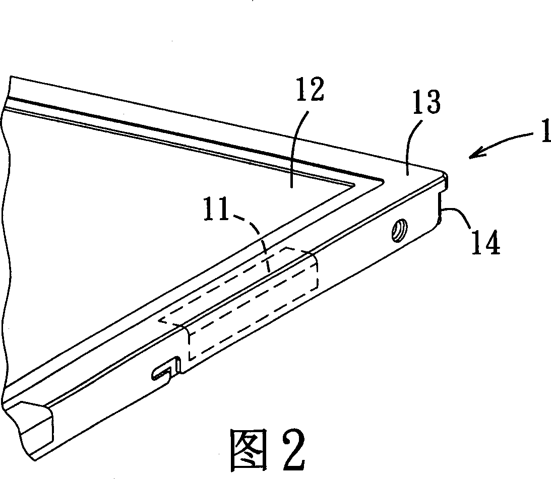
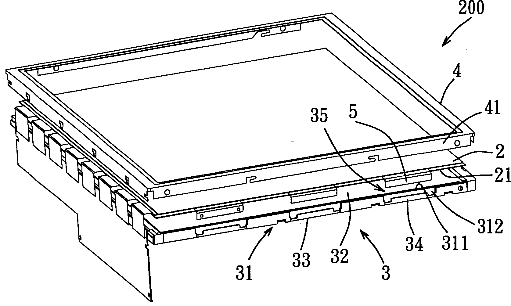
[0035] Refer to image 3 4, the liquid crystal panel module 200 with the flip-chip film limiting device in the first preferred embodiment of the present invention includes a liquid crystal panel 2, a base 3, and an outer frame 4. The liquid crystal panel 2 is electrically connected with several chips on film (COF) 5 on a selected side 21 at intervals and thermally pressed. Each chip on film 5 includes a driveable liquid crystal panel. Since the structure, composition and function of the chip 2 (not shown) and the film covering the chip are known to those skilled ...


PUM


Abstract

The module includes a liquid crystal faceplate, a base, and an outline border bonded the base. Multiple pieces of polycrystalline film with spacer connected electrically are installed on selected side of the liquid crystal faceplate. The base possesses accommodation space enclosed by stand-up sidewalls for the liquid crystal faceplate to be placed. Position-limited parts are setup at outside of the vertical sidewalls corresponding to places, where pieces of polycrystalline film are installed. Multiple pieces of polycrystalline film are bent and constrained on position limited parts so that in procedure of assembling module, pieces of polycrystalline film will not be scratched caused by pressing outline border together. Therefore, unflavored influence on polycrystalline film in assembled module caused by vibration of force can be avoided, so as to raise ratio of fine products.

Description

【Technical Field】 [0001] The present invention relates to a liquid crystal panel module, and in particular to a liquid crystal panel module capable of limiting a chip-on-chip film to avoid damage during the assembly process. 【Background technique】 [0002] Refer to figure 1 As shown in Figure 2, Chip on Film (COF) 11 is a driving unit for TFT-LCD, usually attached to the side of liquid crystal panel 12 by hot pressing, and finally combined with iron The frame 13 and the backlight module 14 are assembled into a liquid crystal panel module (LCD module) 1. [0003] During the assembly process of the existing LCD module 1, the chip-on-chip film 11 on the side of the printed circuit board on the liquid crystal panel 12 is not connected. Due to the toughness of its own material, it is hot pressed and attached to the liquid crystal panel 12 and one of its free ends is exposed. And is suspended on the liquid crystal panel 12. When the iron frame 13 is assembled, the iron frame 13 will b...

Claims


Application Information

Patent Timeline
Patent Type & Authority Applications(China)
IPC IPC(8): G02F1/133H01L21/56
Inventor 邱德欣廖正民玉鸿典
Owner CHUNGHWA PICTURE TUBES LTD
Why Eureka
Try Eureka