Electromagnet control device

A control device and electromagnet technology, applied in the direction of electromagnets with armatures, electromagnets, emergency protection devices, etc., can solve problems such as high input impedance, inability to conduct, and circuit interference can not be prevented well, so as to eliminate interference Influence and reduce the effect of input impedance

Active Publication Date: 2006-08-09
CHANGSHU SWITCHGEAR MFG CO LTD (FORMER CHANGSHU SWITCHGEAR PLANT)
View PDF0 Cites 6 Cited by
  • Summary
  • Abstract
  • Description
  • Claims
  • Application Information

AI Technical Summary

Problems solved by technology

[0004] Due to the high input impedance of this circuit, the interference of other factors to this circuit cannot be well prevented, such as electrostatic interference, electromagnetic field interference, etc. These interferences can make the capacitor C2' precharge, so that when the normal closing and opening, due to no longer Charge the capacitor C2', so that the field effect transistor VT1' cannot be turned on, and the electromagnet does not pull in

Method used


Image

  • Electromagnet control device
  • Electromagnet control device
  • Electromagnet control device

Examples


Embodiment Construction

[0015] The present invention will be further described below in conjunction with the accompanying drawings and embodiments.

[0016] Such as figure 2 , 3 , 4 shown.

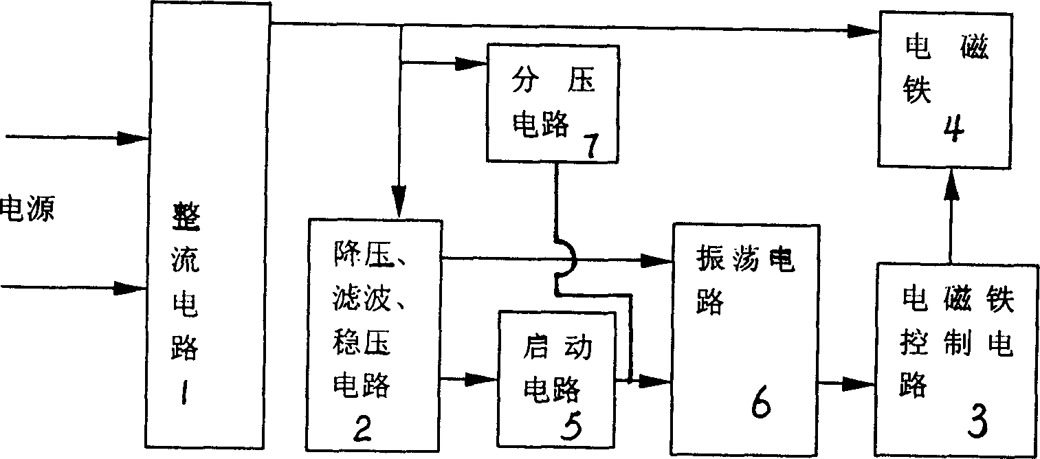
[0017] Such as figure 2 As shown, the electromagnet control device of the present invention includes a rectifier circuit 1, a step-down filter voltage stabilization circuit 2, an electromagnet control circuit 3, an electromagnet 4, a starting circuit 5, and a voltage divider circuit 7, and the rectifier circuit 1 will be rectified The final DC voltage is provided to the electromagnet 4, the voltage divider circuit 7 and the step-down filtering and stabilizing circuit 2, the step-down filtering and stabilizing circuit 2 outputs the working power to the starting circuit 5, and the electromagnet control circuit 3 controls the electromagnet 4 to pull in and release work, the input of the starting circuit 5 is connected to the output of the step-down filtering and stabilizing circuit 2, the output of the voltage ...


PUM


Abstract

The new electromagnet control device with oscillating circuit includes rectification circuit, reduction voltage filtering voltage stabilizing circuit, electromagnet control circuit, electromagnet, start circuit, divider circuit. Input of the rectification circuit is connected to mains supply, and output of the circuit provides operational power supply for each circuit. Input of the start circuit is connected to output of the reduction voltage filtering voltage-stabilizing circuit. Electromagnet control circuit controls electromagnet to carry out operation of attracting and releasing. Output of the divider circuit is connected to output of the start circuit. Characters are that an oscillating circuit is connected between output of the start circuit and input of the electromagnet control circuit. Advantages are: simple structure and high capability for anti interference.

Description

technical field [0001] The invention relates to a control device of a low-voltage circuit breaker, in particular to an electromagnet control device in the circuit breaker. Background technique [0002] Typically, this electromagnet control device can be applied to circuit breaker accessories, such as shunt release and closing electromagnet. Of course, this electromagnet control device is not limited to the above occasions, and can be used to control electromagnetic All occasions for iron attraction and release. [0003] At present, the control circuit of the electromagnet control device in the common circuit breaker is as follows: figure 1 shown. The grid voltage is rectified by diodes D1', D2', D3', and D4' to output DC voltage U1', U1' is divided by resistors R1' and R2', and then passed through diode D5', capacitor C1', Zener diode D6', The resistor R3' smooths and filters the output voltage U2', and U2' charges the capacitor C2'. During the charging process, a voltage...

Claims


Application Information

Patent Timeline
IPC IPC(8): H01H71/00H01H71/68H01H9/54H01F7/18
Inventor 管瑞良毛振风俞晓峰
Owner CHANGSHU SWITCHGEAR MFG CO LTD (FORMER CHANGSHU SWITCHGEAR PLANT)
Why Eureka
Try Eureka