Coplanar coupled-fed multiband antenna for the mobile device

a multi-band antenna and coupled-fed technology, applied in the direction of resonant antennas, antenna supports/mountings, radiating element structural forms, etc., to achieve good impedance matching, reduce inductive reactance, and effectively increase capacitive reactan

Active Publication Date: 2011-04-26
ACER INC
View PDF3 Cites 10 Cited by
  • Summary
  • Abstract
  • Description
  • Claims
  • Application Information

AI Technical Summary

Benefits of technology

[0011]Preferably, in the antenna of the present invention, the radiating portion further comprises a first metal portion and a second metal portion which both resonate at the ¼-wavelength mode. The first metal portion is used to excite the upper band of the antenna, and the second metal portion is used to excite the lower band. By the coplanar coupling feed, the real-part input impedance of the lower band (¼-wavelength resonant mode of the second metal portion) can be reduced. The gap between the second metal portion and the first metal portion can be adjusted to increase the capacitive reactance effectively, and reduce the inductive reactance of the lower band (¼-wavelength resonant mode of the second metal portion) and additionally increase the zero point of the imaginary-part input impedance near the ¼-wavelength resonant frequency. By adjusting the size of the shorting metal portion properly, good impedance matching can be achieved, and the radiating portion can achieve dual resonance for the lower band to cover the global mobile communication system (GSM850, 824˜894 MHz) and (GSM900, 890˜960 MHz) required in for WWAN operation. The upper band of the antenna is a wideband mode excited by the first metal portion and covers the digital communication system (DCS, 1710˜1880 MHz), personal communication system (PCS, 1850˜1990 MHz) and universal mobile telecommunications system (UMTS, 1920˜2170 MHz).

Problems solved by technology

It is a great challenge for the conventional planar inverted-F antenna to use single resonance path to realize GSM850 / 900 operation in the lower band with a limited space.

Method used


Image

  • Coplanar coupled-fed multiband antenna for the mobile device
  • Coplanar coupled-fed multiband antenna for the mobile device
  • Coplanar coupled-fed multiband antenna for the mobile device

Examples


Embodiment Construction

[0022]Exemplary embodiments of the present invention are described herein in the context of the coplanar coupled-fed multiband antenna for mobile communication.

[0023]Those of ordinary skilled in the art will realize that the following detailed description of the exemplary embodiment(s) is illustrative only and is not intended to be in any way limiting. Other embodiments will readily suggest themselves to such skilled persons having the benefit of this disclosure. Reference will now be made in detail to implementations of the exemplary embodiment(s) as illustrated in the accompanying drawings. The same reference indicators will be used throughout the drawings and the following detailed description to refer to the same or like parts.

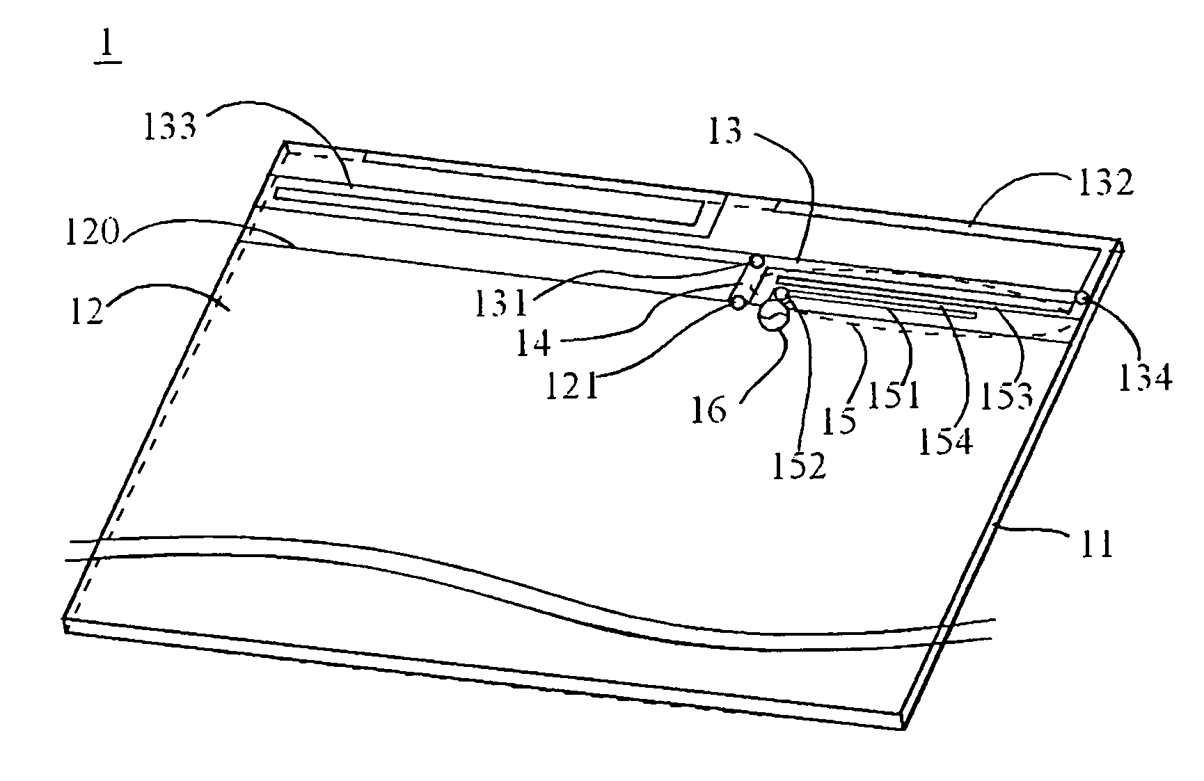
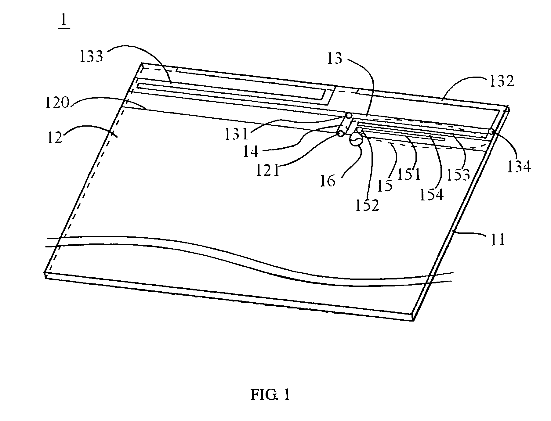
[0024]FIG. 1 illustrates a structural drawing of first embodiment of an antenna in the present invention. The antenna comprises a dielectric substrate 11, a ground plane 12, a radiating portion 13, a shorting metal portion 14, and a feeding portion 15.

[002...


PUM


Abstract

The present invention is related to a coplanar coupled-fed multiband antenna for the mobile communication device. The antenna mainly comprises a dielectric substrate, a ground plane located on one surface of the dielectric substrate, and a radiating portion, a shorting metal portion, and a feeding portion, which are all on the same surface of the dielectric substrate near one edge of the ground plane. One end of the shorting metal portion is connected to the radiating portion, and the other end is connected to the ground plane. The feeding portion comprises a first feeding metal portion and a second feeding metal portion. The first feeding metal portion has a feeding point for the antenna. One end of the second feeding metal portion is connected to the radiating portion, and there is a gap between the second feeding metal portion and the first feeding metal portion.

Description

BACKGROUND OF THE INVENTION[0001]1. Field of the Invention[0002]The present invention is related to a multiband antenna for mobile communication, particularly to a coplanar coupled-fed multiband antenna for mobile communication.[0003]2. Description of the Related Art[0004]With the great development of wireless communication, various wireless communication technologies and products are progressing and appearing constantly. Various mobile phones appear consequently and the original dual-band operation of the mobile phone is improved to multiple-band operation to satisfy the demand for the mobile phones with more communication bands. It is a great challenge for the conventional planar inverted-F antenna to use single resonance path to realize GSM850 / 900 operation in the lower band with a limited space. For example, Taiwan Patent Publication No. 490,884 of “Dual-band inverted-F patch antenna and the radiating metal sheet” disclosed an inverted-F patch antenna to realize the dual-band op...

Claims


Application Information

Patent Timeline
Patent Type & Authority Patents(United States)
IPC IPC(8): H01Q1/24H01Q5/15
CPCH01Q1/38H01Q9/285H01Q9/26
Inventor WONG, KIN-LUHUANG, CHIH-HUNG
Owner ACER INC
Why Eureka
Try Eureka