Clock generator circuit and related method for generating output clock signal

A clock generation circuit and clock signal technology, applied in the direction of generating/distributing signals, delay line pulse generation, single pulse train generator, etc.

Inactive Publication Date: 2006-08-09
MEDIATEK INC
View PDF0 Cites 6 Cited by
  • Summary
  • Abstract
  • Description
  • Claims
  • Application Information

AI Technical Summary

Problems solved by technology

In the prior art clock generation circuit 100, the generated output clock signal C OUT The selectable frequencies are limited, and the number of selectable frequencies is mainly determined by the number N of reference clock signals input to the multiplexer 120. There is no way to provide more frequency options according to the needs of the back-end circuit. output clock signal

Method used


Image

  • Clock generator circuit and related method for generating output clock signal
  • Clock generator circuit and related method for generating output clock signal

Examples


Embodiment Construction

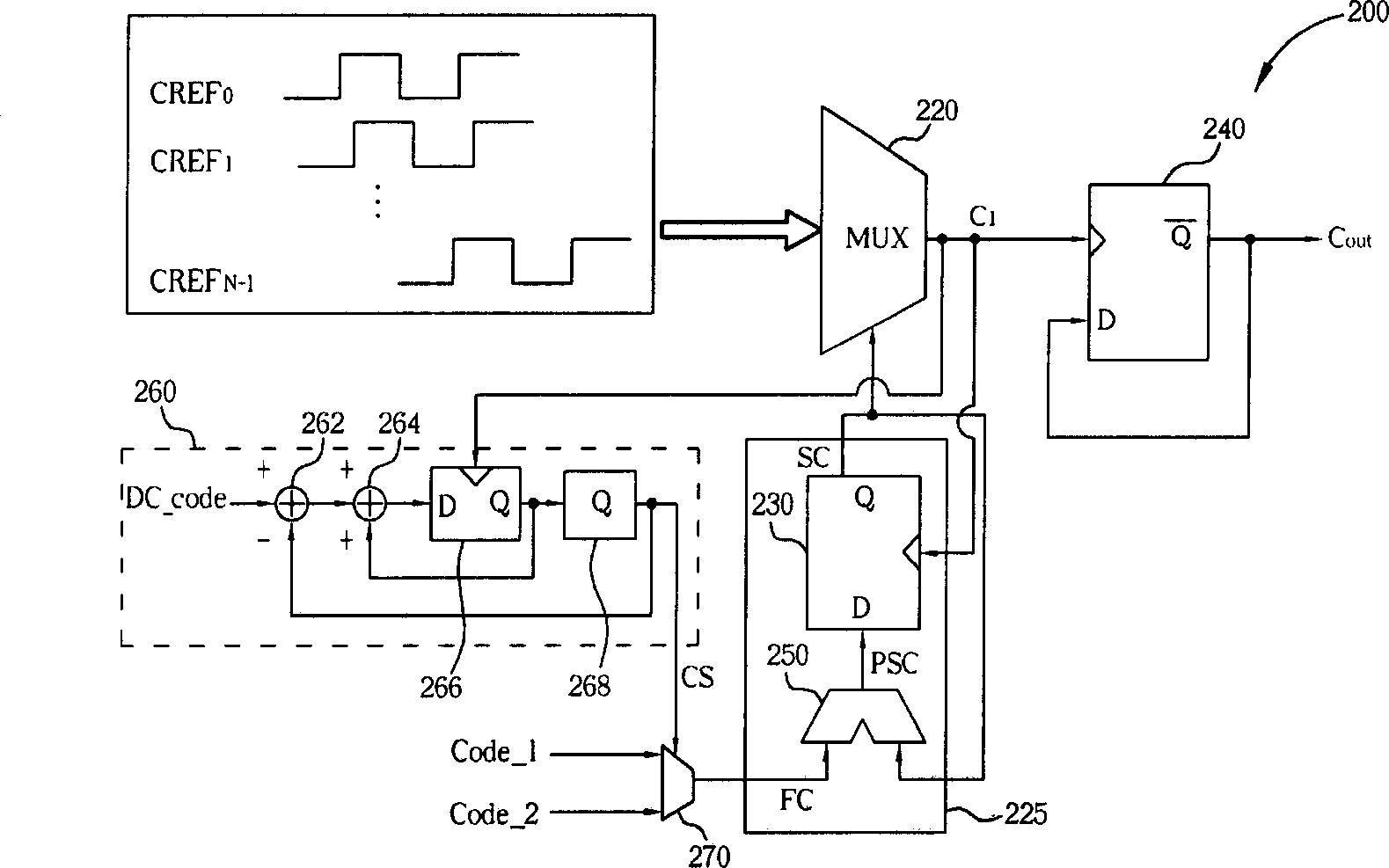
[0019] see figure 2 It is a schematic diagram of an embodiment of the clock generation circuit of the present invention. A clock generating circuit 200 shown in FIG. 2 includes a first multiplexer (multiplexer) 220, an accumulator 225, a toggle circuit (toggle circuit) 240, and a random frequency code generator. The random frequency code generator includes a random signal generator 260 and a second multiplexer 270 . The accumulator 225 includes a register 230 and an adder 250 . In this embodiment, the register 230 is implemented by a first D-flipflop (D-flipflop) 230 , and the trigger circuit 240 is implemented by a second D-flipflop 240 . The signals input to the multiplexer 220 include N reference clock signals in total. N reference clock signals have the same period T REF , the same frequency f REF , but with different phases, where every two adjacent reference clock signals (such as CREF 0 with CREF 1 ) between the phase difference is equal to T REF / N. In other ...


PUM


Abstract

The present invention discloses a clock generator circuit for generating an output clock signal. The clock generator circuit includes: a random frequency code generator for generating a frequency code randomly, wherein the random frequency code generator is clocked by a first clock signal; an accumulator electrically connected to the random frequency code generator, for generating a selection code by accumulating the frequency code, wherein the accumulator is clocked by the first clock signal; a first multiplexer electrically connected to the accumulator, for selecting one of a plurality of reference clock signals as the first clock signal according to the selection code; and a toggle circuit electrically connected to the first multiplexer, being clocked by the first clock signal for generating the output clock signal. The invention can generate output clock signals selected with much more frequency.

Description

technical field [0001] The present invention relates to a clock generation circuit, in particular to a clock generation circuit and method for generating output clock signals with multiple selected frequency characteristics. Background technique [0002] In today's common electronic systems, different integrated circuits (integrated circuit, IC) often have the need to perform synchronous (synchronous) operation. In this type of system, it must be based on a basic system clock (or a synchronous pulse ), to generate periodic clock signals in an appropriate way to drive different circuit functions to operate synchronously. [0003] The figure is a schematic diagram of a clock generation circuit in the prior art. figure 1 The clock generating circuit 100 shown includes a multiplexer 120 , an accumulator 125 , and a toggle circuit 140 . The accumulator 125 is composed of a register 130 and an adder 150 , and the register 130 is realized by a first D-flip flop 130 . The trigger...

Claims


Application Information

Patent Timeline
Patent Type & Authority Applications(China)
IPC IPC(8): H03K3/78H03K3/86
CPCG06F1/08
Inventor 陈昱仰
Owner MEDIATEK INC
Why Eureka
Try Eureka