Shear assisted solid state weld and method of forming

一种剪切位移、焊接方法的技术,应用在制造金属焊件领域,达到滑动小、微观结构受干扰小、消除初始相对速度的效果

Inactive Publication Date: 2006-08-09
NOETIC TECH INC
View PDF5 Cites 4 Cited by
  • Summary
  • Abstract
  • Description
  • Claims
  • Application Information

AI Technical Summary

Problems solved by technology

[0015] This modified friction welding method, while avoiding the brittleness of the "modified diffusion weld" taught by Alford et al. or motion coupled with the need for substantial kinetic energy input

Method used


Image

  • Shear assisted solid state weld and method of forming
  • Shear assisted solid state weld and method of forming
  • Shear assisted solid state weld and method of forming

Examples


Embodiment Construction

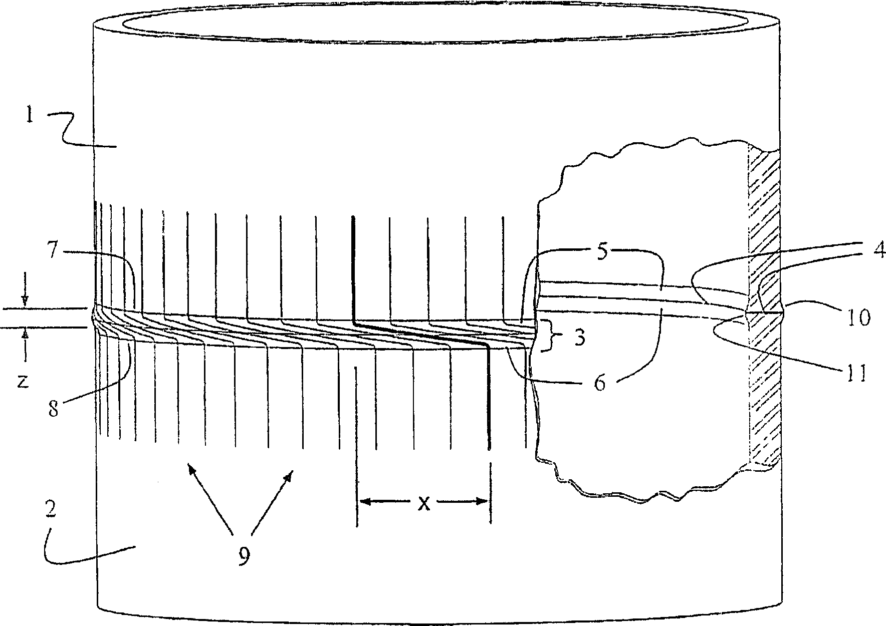
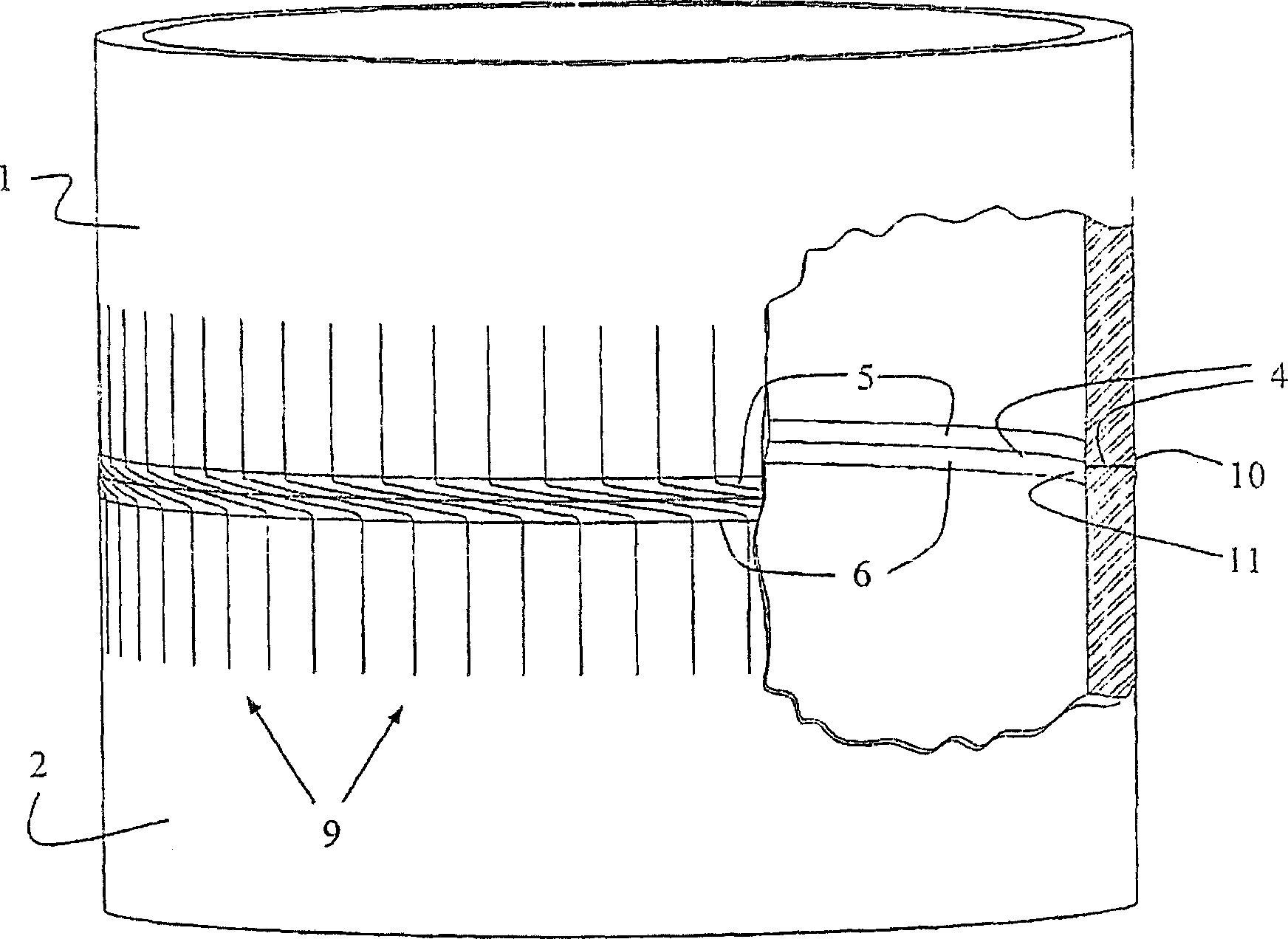
[0071] figure 1 Shown is a shear assisted solid state weld occurring in a welded pipe formed by the preferred method of the present invention. exist figure 1 In the process, a first metal tubular workpiece 1 is coaxially welded to a second metal tubular workpiece 2 to form a weld zone 3 . The weld zone 3 is bisected by a bond line 4 and is generally defined by first and second heat-affected zones 5 and 6 on the weld ends 7 and 8 of the first and second workpieces, respectively. .

[0072] According to a preferred method of the invention, the shear for activating the bond in the weld zone 3 is input as a unidirectional coaxial relative rotation between the workpieces 1 and 2, as described above. In this case, the axial reference lines drawn along the workpieces 1 and 2 are distorted before welding and appear after welding as curve 9, which shows the plastic shear distortion imposed by the welding process. Obviously, the most oblique line has the largest local strain. Most ...


PUM


Abstract

A shear-assisted solid state welding method for joining of metal parts, involves a first step of heating opposing surfaces in a non-passivating environment to a temperature in the hot working temperature range of the metal. A second step involves bringing the opposing surfaces into contact while still in the hot working temperature range, and applying compressive stress sufficient to substantially prevent sliding in response to shear displacement, causing plastic flow in the hot layers. A third step involves imposing relative shear displacement of the metal work pieces without disengaging the opposing surfaces. The shear displacement induces plastic shear strain within the hot layers to progressively induce bonding.

Description

technical field [0001] The present invention relates to methods of making metal weldments. More particularly, the present invention relates to a method of rapidly joining metal workpieces having locally heated mating surfaces that are in contact in a non-oxidizing or non-passivating environment by introducing shear strain into the materials adjacent the contacting surfaces to induce bonding. Background technique [0002] Connecting multiple pipe sections is a major task in the construction of wells and pipelines for the production of oil and other reservoir fluids. Manufacturing costs and quality controls, as well as the technical properties of the resulting connections, lead to the fact that there is always an incentive to pursue more efficient and versatile connections. These requirements are further enhanced by environmental requirements, since most of them are linear systems with little or no margin to mitigate the consequences of even a single connection failure. [0...

Claims


Application Information

Patent Timeline
Patent Type & Authority Applications(China)
IPC IPC(8): B23K13/02B23K13/06B23K20/02B23K20/14B23K20/12
CPCB23K13/025B23K20/129B23K13/06B23K2201/10B23K20/028B23K31/125B23K20/023B23K20/14B23K2101/10
Inventor 莫里斯·W·斯莱克丹尼尔·M·舒特
Owner NOETIC TECH INC
Why Eureka
Try Eureka