Reciprocating petroleum beam-pumping unit with hydraulic transmission

A technology for hydraulic transmission and oil extraction, which is applied in the development of fluids, transmission devices, fluid transmission devices, etc., can solve the problems of low failure, insufficient long-life working performance requirements, etc.

Inactive Publication Date: 2006-08-16
彭利
View PDF1 Cites 10 Cited by
  • Summary
  • Abstract
  • Description
  • Claims
  • Application Information

AI Technical Summary

Problems solved by technology

[0003] Compared with the corresponding products currently in use, although the machine may have obvious advantages in terms of comprehensive economic effects in manufacture and use, the hydraulic components selected for its hydraulic transmission components and the hydraulic system used are reliable in operation. There are still deficiencies in the indicators that can be achieved in terms of working performance, such as safety and working life, and the low failure and long-life working performance requirements that are necessary for this kind of pumping unit products. At the same time, the main structure of the whole machine also needs to be further improved.

Method used


Image

  • Reciprocating petroleum beam-pumping unit with hydraulic transmission
  • Reciprocating petroleum beam-pumping unit with hydraulic transmission
  • Reciprocating petroleum beam-pumping unit with hydraulic transmission

Examples


Embodiment approach

[0016] Here, a typical model of a hydraulically driven oil extraction pumping unit is used as an example to describe the specific implementation of the present invention.

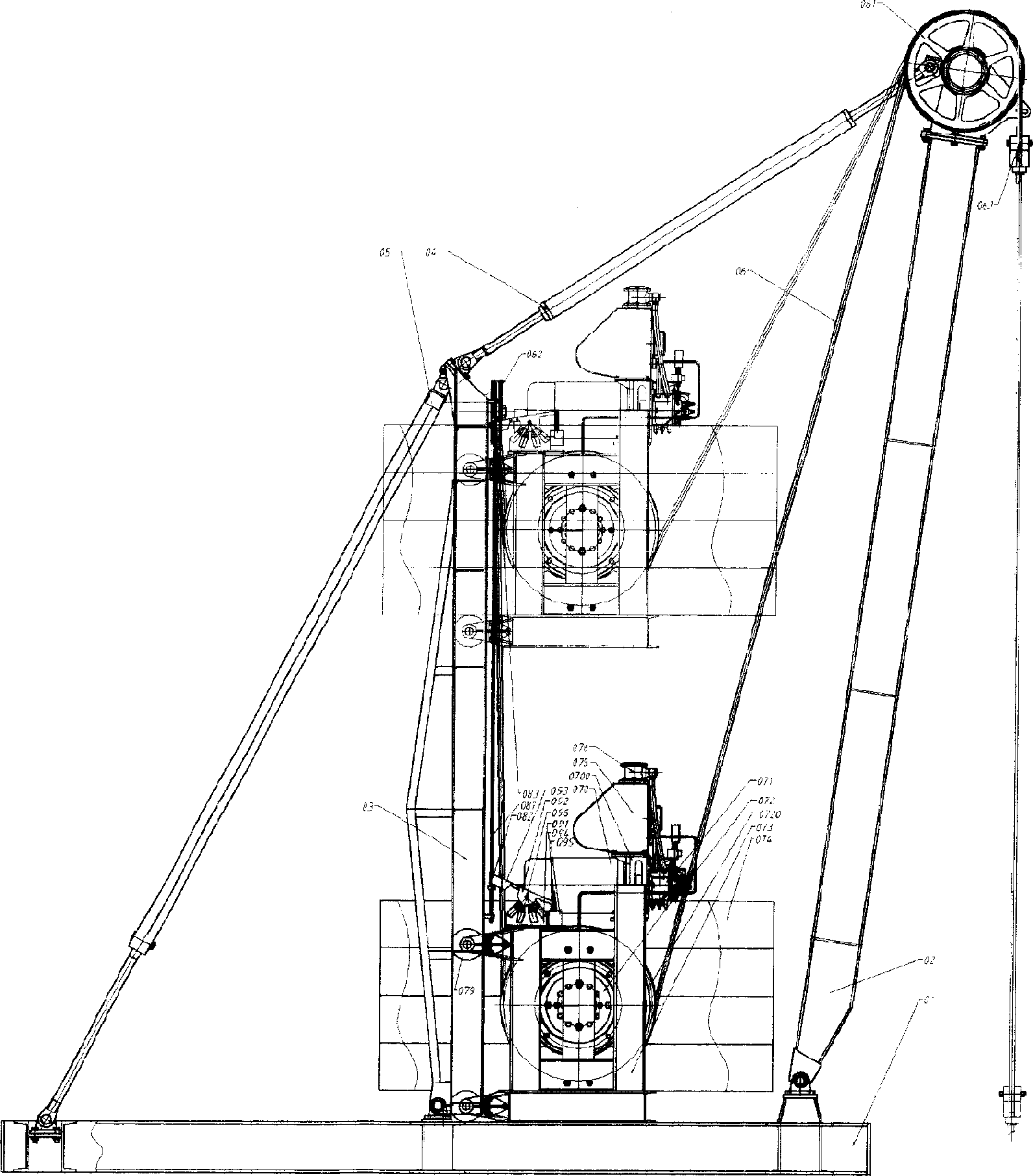
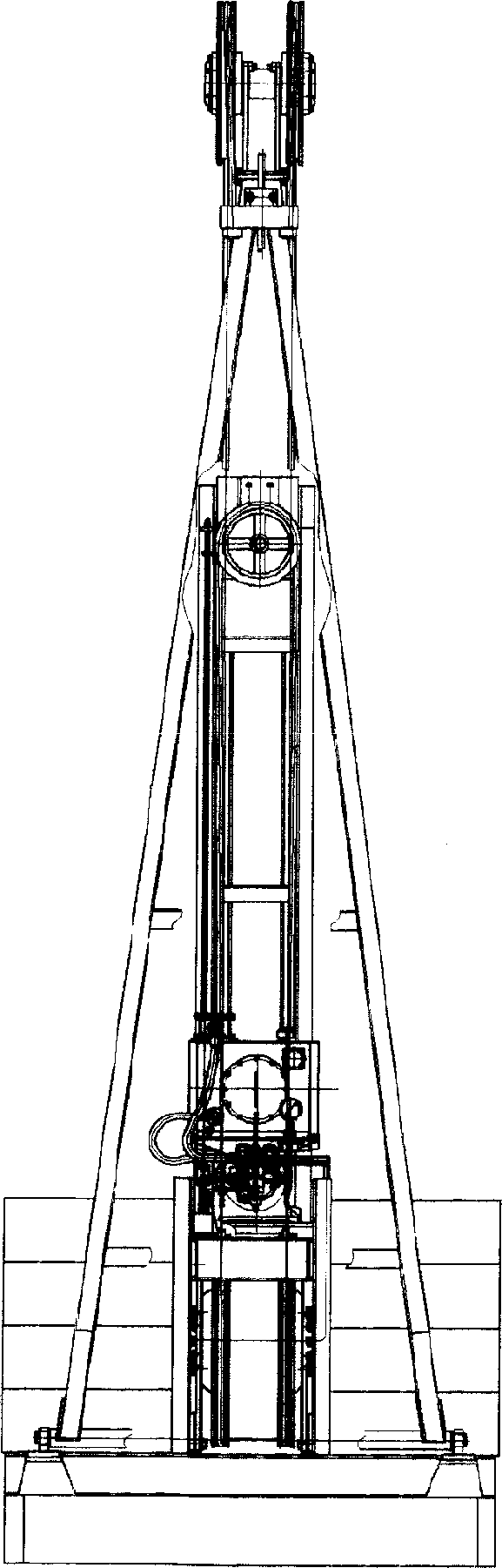
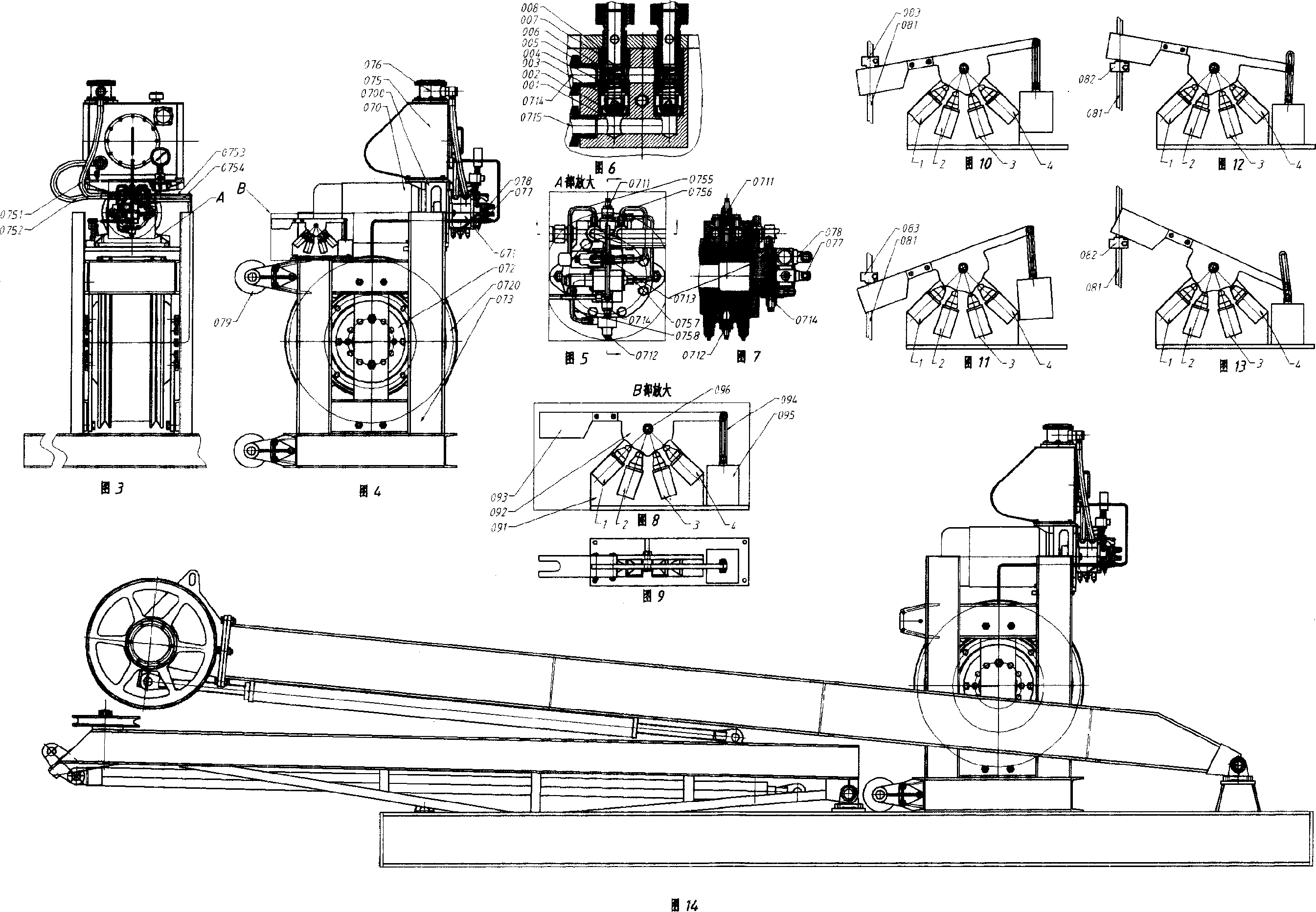
[0017] The overall structure of this embodiment is as figure 1 and figure 2 As shown: the base 01, the front bracket 02, the rear bracket 03, the upper tie rod 04, and the diagonal tie rod 05 are connected by hinges to form a light and stable frame structure. (Also refer to Fig. 3 to Fig. 8) The slider type variable, reversing hydraulic pump 071, motor 070, working fluid tank 075, working fluid return filter 076, control valve and pipeline accessories are connected together by the connection base 0700 It constitutes a hydraulic power source as a whole; the outer circumference of the transmission disc of the low-speed high-torque hydraulic motor 072 driven by the slider type disc is directly assembled with the transmission sheave 0720 with two V-shaped transmission grooves on the outer peripheral surface t...


PUM


Abstract

A hydraulic transmission petroleum mining pumping unit, it compose of foundation, front bracket, rear bracket, up pull-rod and diagonal pull-rod that are connected by hinge, hydraulic transmission assembly is set between front and rear bracket which compose of slide-block type variable and reversing gear hydraulic pump of combinational flat valve, slide-block type plate transmission low-speed torque hydraulic motor, oil-box and accessories group of pipe line, that is the transmission system operates opening pump motor to volume velocity modulation and reversing loop, and combine by hydraulic transmission wheel connecting with transmission pieces of mining pump, control by machined, electric and hydraulic adjustable system to work continuously and reciprocally with the needful stroke and stroke time.

Description

1. Technical field: [0001] The invention relates to a reciprocating oil extraction pumping unit, in particular to a hydraulic transmission reciprocating pumping unit. 2. Background technology: [0002] The background technology closest to the present invention is in the technical scheme of the invention patent application whose application number is 2004100715265, publication number is CN1587751A, and the name is "rotary volumetric hydraulic device and hydraulic transmission type oil extraction pumping unit" Provided is a construction technology of a hydraulic transmission reciprocating oil extraction pumping unit. The pumping unit is a highly integrated hydraulic transmission component assembled on the top of the vertical frame with adjustable inclination angle. The flexible load-bearing traction component matches the transmission structure of the transmission wheel surface of the hydraulic transmission component. The other end of the heavy body is connected with the conne...

Claims


Application Information

Patent Timeline
Patent Type & Authority Applications(China)
IPC IPC(8): E21B43/00F16H47/02
Inventor 彭利彭凌宇
Owner 彭利
Why Eureka
Try Eureka