Method and device for realizing radio-frequency front end with low complexity and super-wide band

A radio frequency front-end and implementation method technology, applied in the field of communication, can solve problems such as design difficulties, and achieve the effect of reducing reception performance

Inactive Publication Date: 2006-08-16
SOUTHEAST UNIV
View PDF0 Cites 15 Cited by
  • Summary
  • Abstract
  • Description
  • Claims
  • Application Information

AI Technical Summary

Problems solved by technology

The greater the bandwidth these circuits s

Method used


Image

  • Method and device for realizing radio-frequency front end with low complexity and super-wide band
  • Method and device for realizing radio-frequency front end with low complexity and super-wide band
  • Method and device for realizing radio-frequency front end with low complexity and super-wide band

Examples


Embodiment Construction

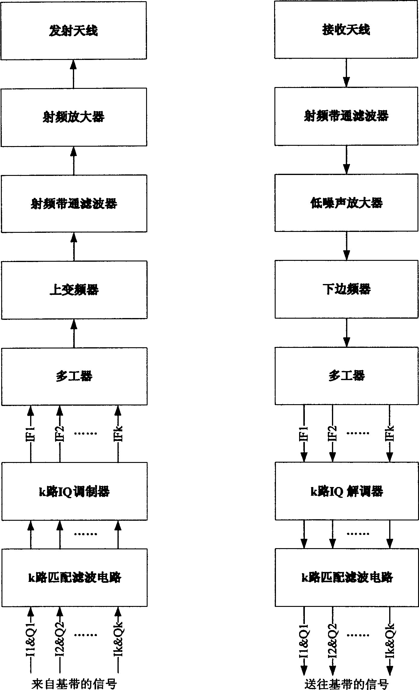
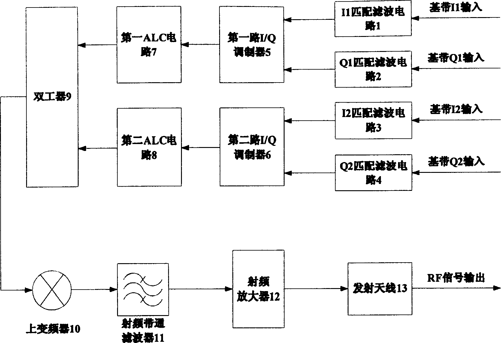
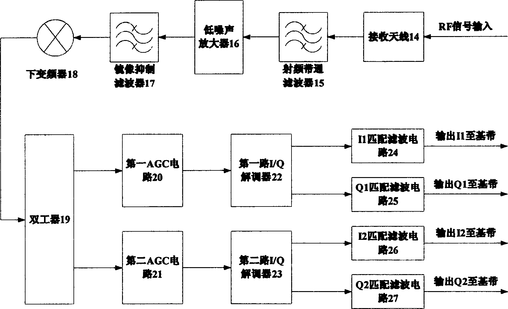
[0014] The invention realizes a low-complexity ultra-wideband radio frequency front-end experimental device on the 3.5GHz frequency band. The RF front-end adopts a dual-carrier broadband modulation scheme, and the combining and splitting of IF signals are completed by duplexers. Center frequencies of the intermediate frequency signals are 1.188GHz and 1.452GHz respectively, and center frequencies of the radio frequency signals are 3.48GHz. The front-end signal communication bandwidth is about 400MHz, and the bandwidth of the two subcarriers and the isolation bandwidth between the subcarriers are both 132MHz. The transmitting power of the transmitter is about -12dBm.

[0015] This device comprises transmitter and receiver two parts, wherein, in transmitter: I 1 Matched filter circuit 1, Q 1 The output terminal of the matched filter circuit 2 is connected to the first road IQ modulator 5, the output terminal of the first road IQ modulator 5 is connected to the first ALC circu...


PUM


Abstract

The invention provides a method for use in implementing an ultra wideband RF front end. It included: medium frequency signals inputted from multi-path wideband are combined at communicator side through multiplexer, and the combined medium frequency signals are up- converted to RF to make a multicarrier transmission so that the difficulty for designing a quadraphase modulator in communicator and a part of high speed A/D converting circuit are reduced.

Description

technical field [0001] The invention relates to an ultra-wideband radio frequency front-end realization method applied to high-speed wireless short-distance communication, and belongs to the technical field of communication. Background technique [0002] In recent years, due to the urgent demand for high-speed wireless short-distance communication in the market, ultra-wideband technology (UWB) has attracted more and more attention. Using the UWB spectrum from 3.1GHz to 10.6GHz, telecom equipment manufacturers and operators can vigorously build and develop wireless personal area networks (WPANs) to achieve low-power, low-cost high-speed wireless data access. Generally speaking, the data transmission of UWB communication system needs to exceed 100Mbps, and its communication bandwidth should reach more than 500MHz. These limitations bring some challenges to the design of high-speed wireless UWB communication system. Among them, such as radio frequency circuits (low noise ampli...

Claims


Application Information

Patent Timeline
IPC IPC(8): H04B1/69H04B1/40H04L25/03
Inventor 洪伟田玲朱红兵
Owner SOUTHEAST UNIV
Why Eureka
Try Eureka