Method and device for power braking with a fluid-operated liquid metal current switch

A liquid metal, current switch technology, used in electrical switches, circuits, electrical components, etc., to achieve fast response time, good reliability, and a small amount of wear and tear

Inactive Publication Date: 2006-08-16
ABB RES LTD
View PDF5 Cites 14 Cited by
  • Summary
  • Abstract
  • Description
  • Claims
  • Application Information

AI Technical Summary

Problems solved by technology

Since the liquid metal body collected in the hose acts as a vehicle detector, there is no independent control device to control the specific on-off of the switch by means of liquid metal

Method used


Image

  • Method and device for power braking with a fluid-operated liquid metal current switch
  • Method and device for power braking with a fluid-operated liquid metal current switch
  • Method and device for power braking with a fluid-operated liquid metal current switch

Examples


Embodiment Construction

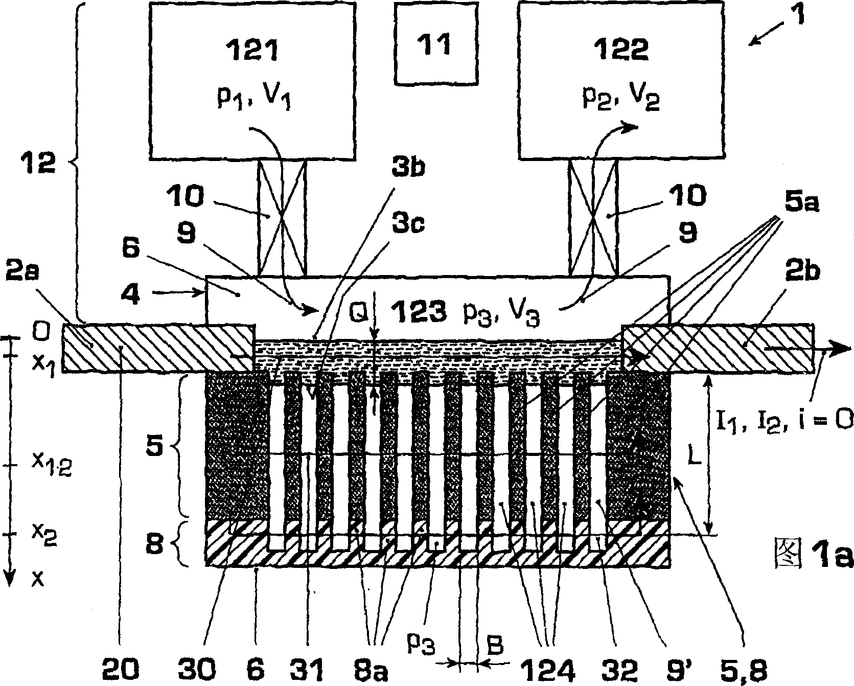
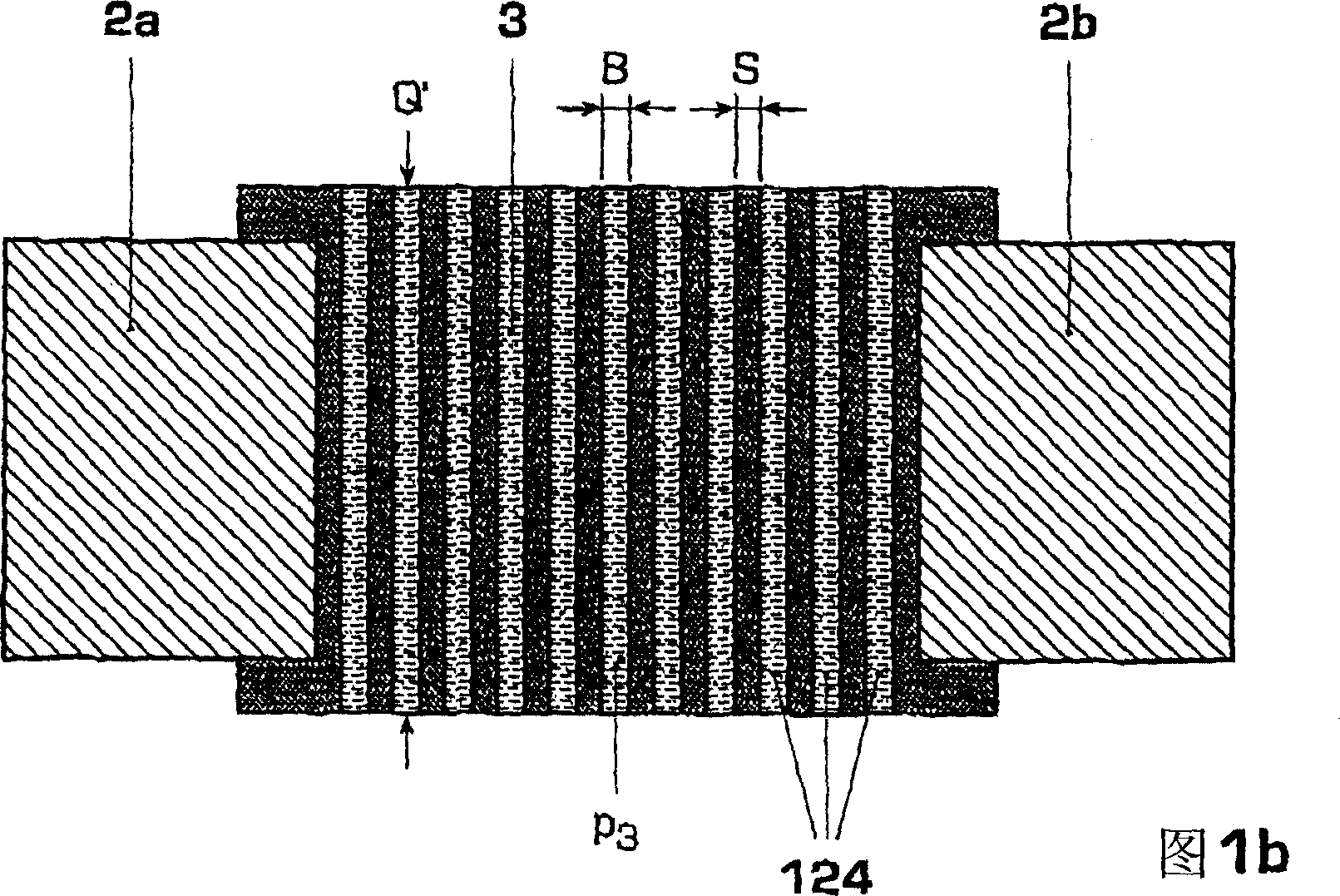
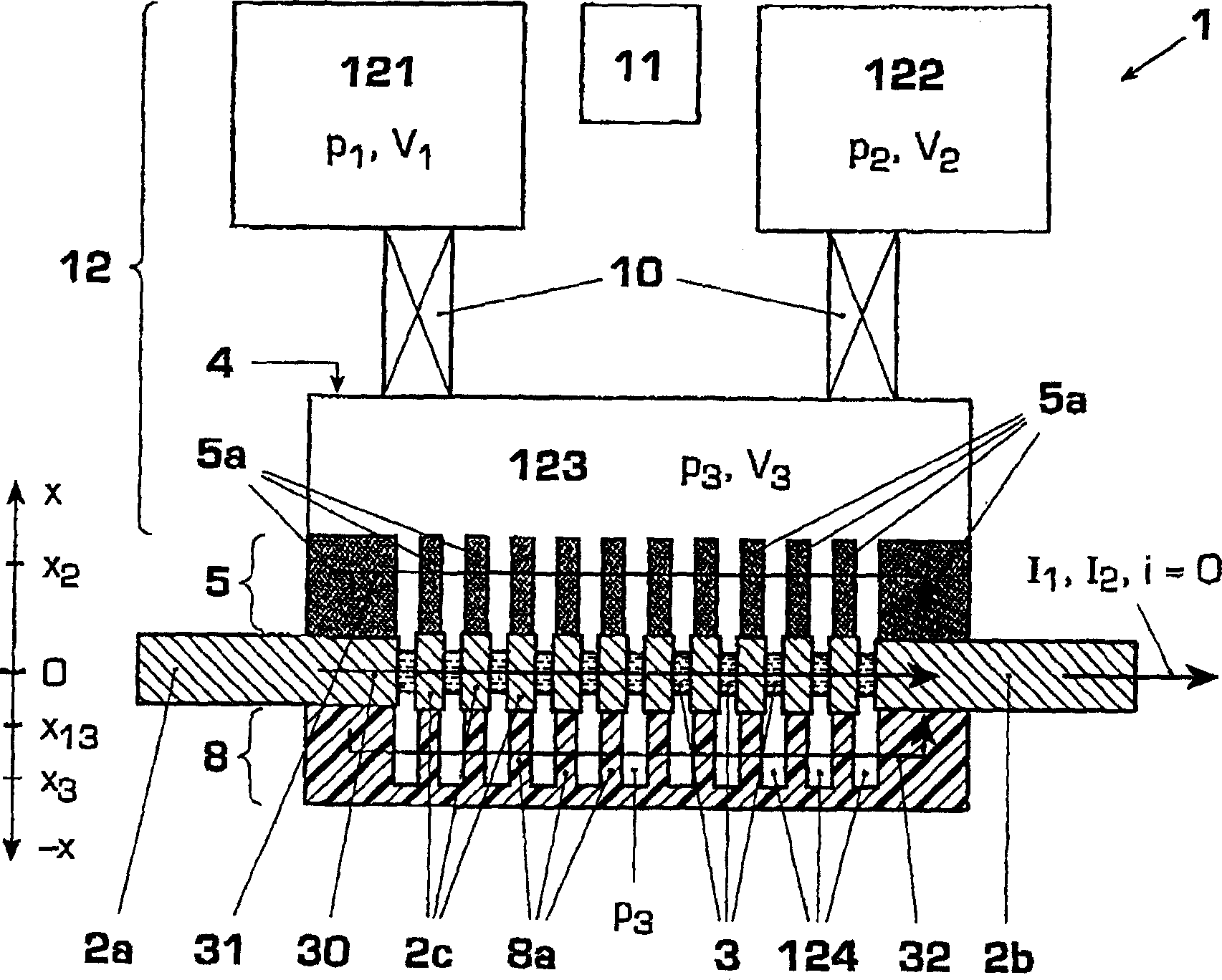
[0027] Figures 1a and 1b show an embodiment of a current switch 1 of the liquid metal type, in particular a current limiter or circuit breaker 1 of the liquid metal type, in cross-section and plan view. The current switch 1 comprises solid metal electrodes 2 a , 2 b for connection to a current source 20 and a container 4 of liquid metal 3 . The container 4 has a bottom 6 of insulating material and a cover 6 , between which a dielectric 5 , 8 , 9 and at least one channel 3 a for the liquid metal 3 are arranged.

[0028] According to the invention, the power switch 1 has a dielectric fluid drive 12 with a control device 11, in which the working fluid 9 operates at a predeterminable drive pressure P 1 , P 2 Act directly on a front side surface 3b of the liquid metal 3 and move the liquid metal body 3 from a first position X 1 Move to a second position X 12 , X 2 middle. in the first position X 1 , the liquid metal 3 is at least partly in the operating current I 1 In the fi...


PUM


Abstract

The invention relates to a method and a device (1) for current limitation and / or power braking and to a switchgear having said device (1). According to the invention, a liquid metal (3) is moved by a dielectric fluid drive mechanism (12) with a control device (11) between a first current path for a nominal current (I1), a second current path (31) for current limitation (12) and optionally a third current path (32) for power braking (i=0), wherein the working fluid (9) exerts a mechanical influence directly upon a surface (3b) of the liquid metal (3) with a predetermined drive pressure (p1, p2). Examples of embodiments are, inter alia, an insulating gas (9) or insulating fluid (9) as drive fluid (9); a pressure drive (12) with pressure vessels (121-124) and valves (10) or a piezo drive mechanism (12) for the working fluid (9); and design criteria for liquid metal array (3a, 4), drive pressure (p1, p2) and piezo drive mechanism (12). Amongst the advantages are reversible current limitation and power braking, which is also suitable for high currents and voltages, rapid reaction times, little wear and easy maintenance.

Description

technical field [0001] The invention relates to the field of basic engineering of electrical switchgear, in particular current limiting and circuit breaking in high-voltage, medium-voltage or low-voltage switchgear. The invention is based on a method and a device for current limiting or disconnection as well as a switching device having the device, as stated in the preambles of the independent claims. Background technique [0002] DE2652506 discloses a high current electrical switch with liquid metal. In one aspect, a liquid metal mixture is applied for wetting the solid metal electrodes and for reducing the contact resistance. In this case, the liquid metal is driven into the contact gap by mechanical actuation, for example via movable contacts or pneumatic submerged pistons, against the direction of gravity. The liquid metal can further be stabilized and fixed in the contact gap by the constriction effect, according to which the current-carrying conductor is subjected to...

Claims


Application Information

Patent Timeline
Patent Type & Authority Applications(China)
IPC IPC(8): H01H29/28
Inventor 卡韦赫·尼亚耶什弗里德里希·柯尼希安德烈亚斯·达尔基斯特
Owner ABB RES LTD
Why Eureka
Try Eureka