Frame synchronization in universal mobile telephone system

A frame synchronization and sub-synchronization technology, applied in radio transmission systems, time division multiplexing systems, synchronization devices, etc., can solve problems such as prolonging user time

Inactive Publication Date: 2010-04-28
THOMSON LICENSING SA
View PDF3 Cites 0 Cited by
  • Summary
  • Abstract
  • Description
  • Claims
  • Application Information

AI Technical Summary

Problems solved by technology

Therefore, the entire cell search process must be restarted, further extending the time the user must wait until voice / data communications can begin

Method used


Image

  • Frame synchronization in universal mobile telephone system
  • Frame synchronization in universal mobile telephone system
  • Frame synchronization in universal mobile telephone system

Examples


Embodiment Construction

[0013] Apart from the inventive concept, the units shown in the figures are well known and will not be described in detail. Furthermore, it is assumed that UMTS-based wireless communication systems are well known and will not be described in detail here. For example, spread spectrum transmission and reception, cell (base station), user equipment (UE), downlink channel, uplink channel, and rake receiver are well known and will not be described here, except for the concept of the present invention. Furthermore, conventional programming techniques can be used to implement the concepts of the present invention, again not illustrated here. Finally, like numbers in the drawings indicate like elements.

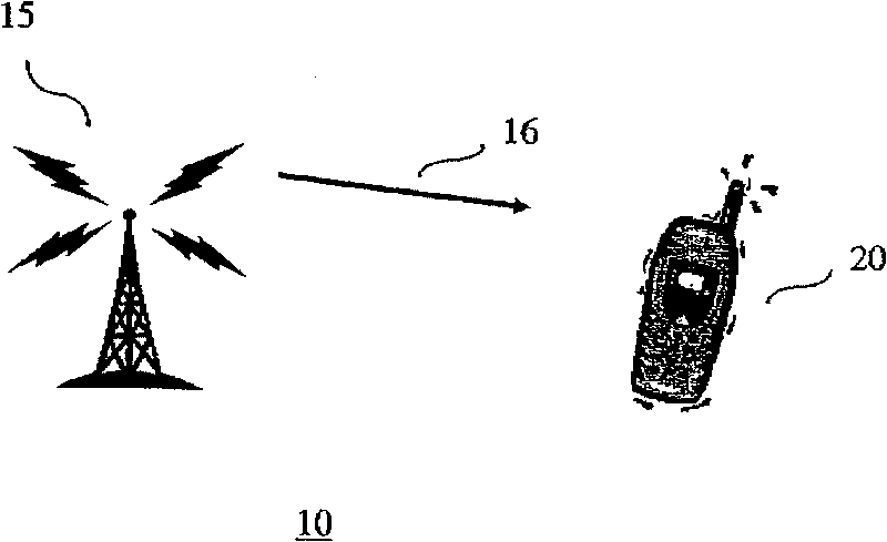
[0014] figure 1 An illustrative portion of a UMTS wireless communication system 10 in accordance with the principles of the present invention is shown in . A cell (or base station) 15 broadcasts a downlink synchronization channel (SCH) signal 16 including the aforementioned PSCH a...


PUM


Abstract

A Universal Mobile Telephone System (UMTS) receiver performs slot synchronization using a received primary synchronization channel (PSCH) (305). Subsequent to completion of slot synchronization, the UMTS receiver performs frame synchronization using a received secondary synchronization channel (SSCH) (320) in such a way that the UMTS receiver uses the received primary synchronization channel (PSCH) to detect a change in channel conditions (325, 330, 335, 350, 355, 360).

Description

technical field [0001] The present invention relates generally to wireless receiving devices, and more particularly to user equipment (UE) in a spread spectrum based wireless system such as the Universal Mobile Telephone System (UMTS). Background technique [0002] The basic unit of time in the UMTS radio signal is the 10 millisecond (ms) radio frame, each divided into 15 time slots of 2560 chips. The UMTS radio signal from the cell (or base station) to the UMTS receiver is the "downlink signal", while the reverse radio signal is called the "uplink signal". When a UMTS receiver is first turned on, the UMTS receiver performs a "cell search" to search for a cell with which to communicate. Specifically, and explained below, initially the UMTS receiver looks for the downlink synchronization channel (SCH) sent from the cell to synchronize to on a slot and frame level and determines the cell specific scrambling code set. Voice / data communication can only be started after a succe...

Claims


Application Information

Patent Timeline
Patent Type & Authority Patents(China)
IPC IPC(8): H04B7/212H04B7/26H04J3/06H04L12/56H04W56/00H04W74/04H04W84/04
CPCH04W74/04H04B1/70735H04B1/7083H04W56/0015H04W92/10H04W84/04H04J3/0608H04J3/0605
Inventor 高文路易斯·罗伯特·利特温
Owner THOMSON LICENSING SA
Why Eureka
Try Eureka