
Camshaft adjuster with play-free locking

A technology of camshaft adjusters and vanes, which is applied to shaft couplings, valve devices, rotary couplings, etc., and can solve problems such as high production costs and complex contour structures

Inactive Publication Date: 2006-08-23
HAIDER RUN CO LTD
View PDF7 Cites 4 Cited by
  • Summary
  • Abstract
  • Description
  • Claims
  • Application Information

AI Technical Summary

Problems solved by technology

Another dimensional design of the center pin is provided in DE 197 42 947 A1, but its contour structure is complex and the production costs are relatively high

Method used


Image

  • Camshaft adjuster with play-free locking
  • Camshaft adjuster with play-free locking
  • Camshaft adjuster with play-free locking

Examples


Embodiment Construction

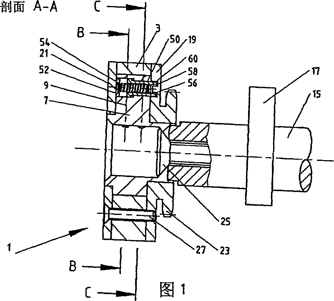
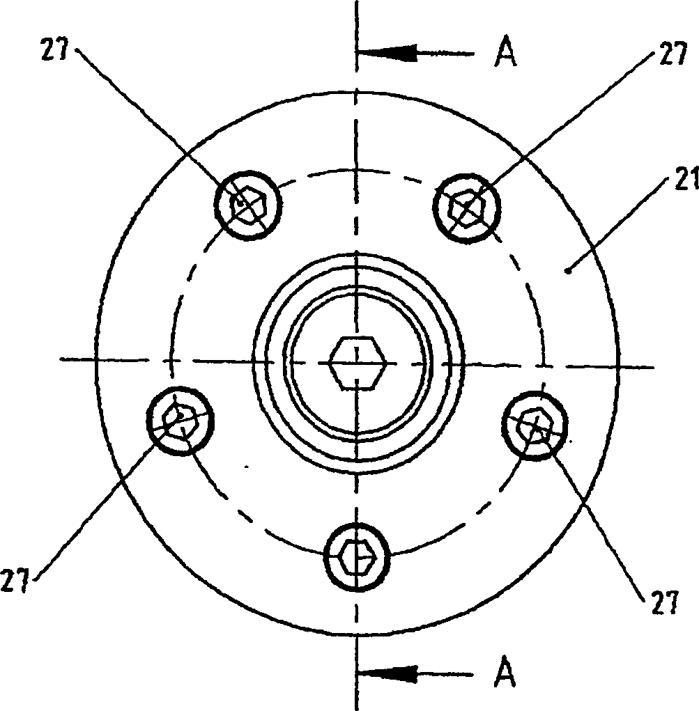
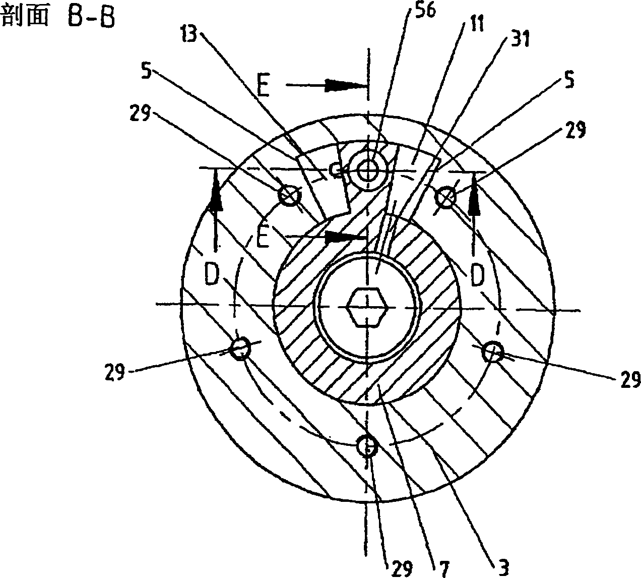
[0027] figure 2 It is a front view of one side of the camshaft adjuster marked in FIG. 1 . See you in other sections image 3 with Figure 4 . The camshaft adjuster 1 meshes with a shaft 15 on which a cam 17 is located. As can be seen from FIG. 1 , the camshaft adjuster can be connected by means of connecting bolts 25 and a form-fit connection between the shaft 15 and the sprocket 23 . The guard plate 21 of the camshaft adjuster 1 is fixed by fasteners such as torque bolts 27 . Housing 19 and shield 21 surround image 3 with Figure 4 Hydraulic chambers 11 and 13 in. Hydraulic chambers 11 and 13 are filled with hydraulic medium through oil pipe 31 . The torque bolt 27 passes through a threaded channel 29 in the stator 3 of the camshaft adjuster 1 . The screw tracks 29 in the stator 3 are preferably in the spacers 5 . Located in the stator 3 is a rotor 7, which may have one or more vanes. image 3 with Figure 4 In the vane 9 is a locking unit 50 with a slide valve ...


PUM


Abstract

Camshaft adjusters according to the swivel motor principle may be provided with a bar which arrests the rotor in a position relative to the stator. A bar according to the invention is provided with two portions, between which a change of power transmission takes place during the arresting process.

Description

technical field [0001] The subject matter of the invention is a camshaft adjuster with a backlash-free locking device according to the general concept of claim 1 . Background technique [0002] There are many types of camshaft adjusters. In addition to camshaft adjusters with helical toothing, there are also many camshaft adjusters based on the principle of reversing electric motors. Reversing motor camshaft adjusters generally have a housing, which is also referred to as a stator, in which a rotor with any number of vanes rotates. Between the spacers of the stator, and between the vanes of the rotor, hydraulic chambers are formed that contain hydraulic fluid, such as motor oil. The freedom of movement between the rotor and stator can be restricted or impeded by adding slide valves. Such spool valves or locking pins are usually also fitted with pre-tensioned springs. Only after overcoming the spring force will the spool move to the release position. Subsequent hydraulic...

Claims


Application Information

Patent Timeline
Patent Type & Authority Applications(China)
IPC IPC(8): F16D33/00F01L1/344
CPCF01L1/3442F01L2001/34453F01L2001/34469B29D28/00B26F1/18B26F1/24B29C65/04B29C66/02242
Inventor 斯特芬·施魏策尔
Owner HAIDER RUN CO LTD
Learn More