Novel composite position controller

A level controller and composite technology, applied in the direction of liquid level control, non-electric variable control, control/adjustment system, etc., can solve the problem of compounding, reduce the impact resistance and reliability of the instrument, and the length of the whole machine should not be too short and other problems, to achieve the effects of shortened length, easy maintenance, and improved reliability

Inactive Publication Date: 2006-08-23
杜国凯
View PDF1 Cites 9 Cited by
  • Summary
  • Abstract
  • Description
  • Claims
  • Application Information

AI Technical Summary

Problems solved by technology

Since the composite detection component in the previous application file fixes the detection electrode and the insulating part together, firstly, the length of the whole machine cannot be too short, and secondly, the cantilever is too long, which gr

Method used


Image

  • Novel composite position controller
  • Novel composite position controller

Examples


Embodiment Construction

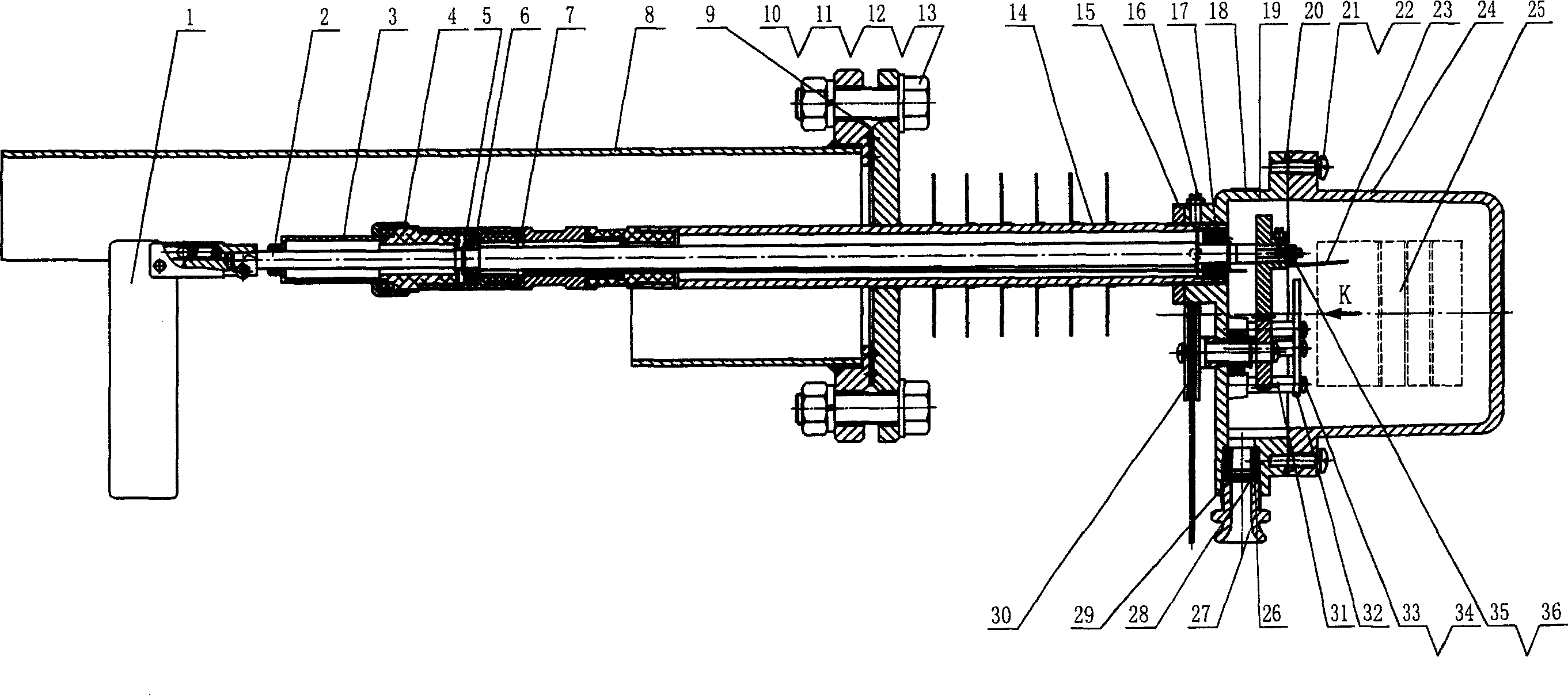
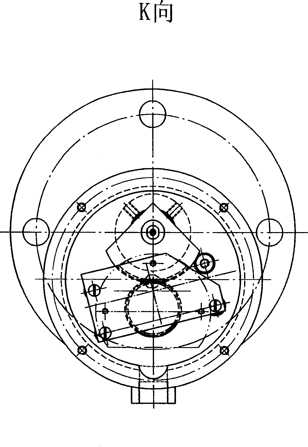
[0021] The present invention will be described in detail below with reference to the accompanying drawings.

[0022] As shown in the figure: put the adjustment pad on the insulating joint of the composite probe assembly 4 and then screw it into the shaft cylinder of the shaft cylinder assembly 14, and tighten it. Put a Teflon gasket on the shielding pole, and then tighten it with the insulating joint. Put the shielding lead wire assembly 7 into the shielding pole, after the shielding pole lead wire passes through the small hole of the shaft cylinder and the sliding bearing 17, tighten the shaft cylinder of the sliding bearing 17. Put the adjusting pad 29 into the shielding pole on the bearing outer shell of the composite probe assembly 4, and compress the flat pad. Penetrate the rolling bearing 6 on the main shaft 2, fix it firmly with the circlip 5 for the shaft, then put the shaft cylinder through which the main shaft 2 passes and the large hole of the sliding bearing 17, a...


PUM


Abstract

This invention relates to a new type of compound position controller including a test board component, a master shaft, a sealing component, a compound detection pole component, a screen leading component, a protecting cover component, a beam barrel, a base seat, a detection pole lead, a top cover, a CB component and a manual component, in which, the insulation connector of the compound detection pole component is screwed in the beam barrel to be fastened, a screen pole is screwed on the bearing jacket of the compound detection pole compound and the bearing jacket is screwed on the casing cap of the compound.

Description

technical field [0001] The invention relates to a controller, in particular to a material level control instrument applied in the field of solid material level. Background technique [0002] At present, there are many types of contact material level controllers, such as resistance-moving type, resistance-rotation type, tuning fork type, capacitive type, radio frequency admittance type, etc. Due to the complex working conditions of the materials in the silo, general material level controllers are inconvenient to use. For example: when it is necessary to actually verify whether there is material in the silo in order to determine the debugging status of the electronic material level controller, the controller can only be determined by removing the controller to see the actual status of the material in the silo, which is very inconvenient. Because the material situation in the silo is very complicated, there is often a malfunction of the material level controller. At this time,...

Claims


Application Information

Patent Timeline
IPC IPC(8): G05D9/00G01F23/284
Inventor 杜国凯
Owner 杜国凯
Why Eureka
Try Eureka