Moisture sensor device and self-diagnosing method therefor
A humidity sensing and sensor technology, which is applied in the direction of instruments, scientific instruments, drying rooms/containers, etc., can solve problems such as difficult equipment and inability to perform self-diagnosis, and achieve the effect of increasing capacitance changes and improving sensitivity
- Summary
- Abstract
- Description
- Claims
- Application Information
AI Technical Summary
Problems solved by technology
Method used
Image

Examples
no. 1 example
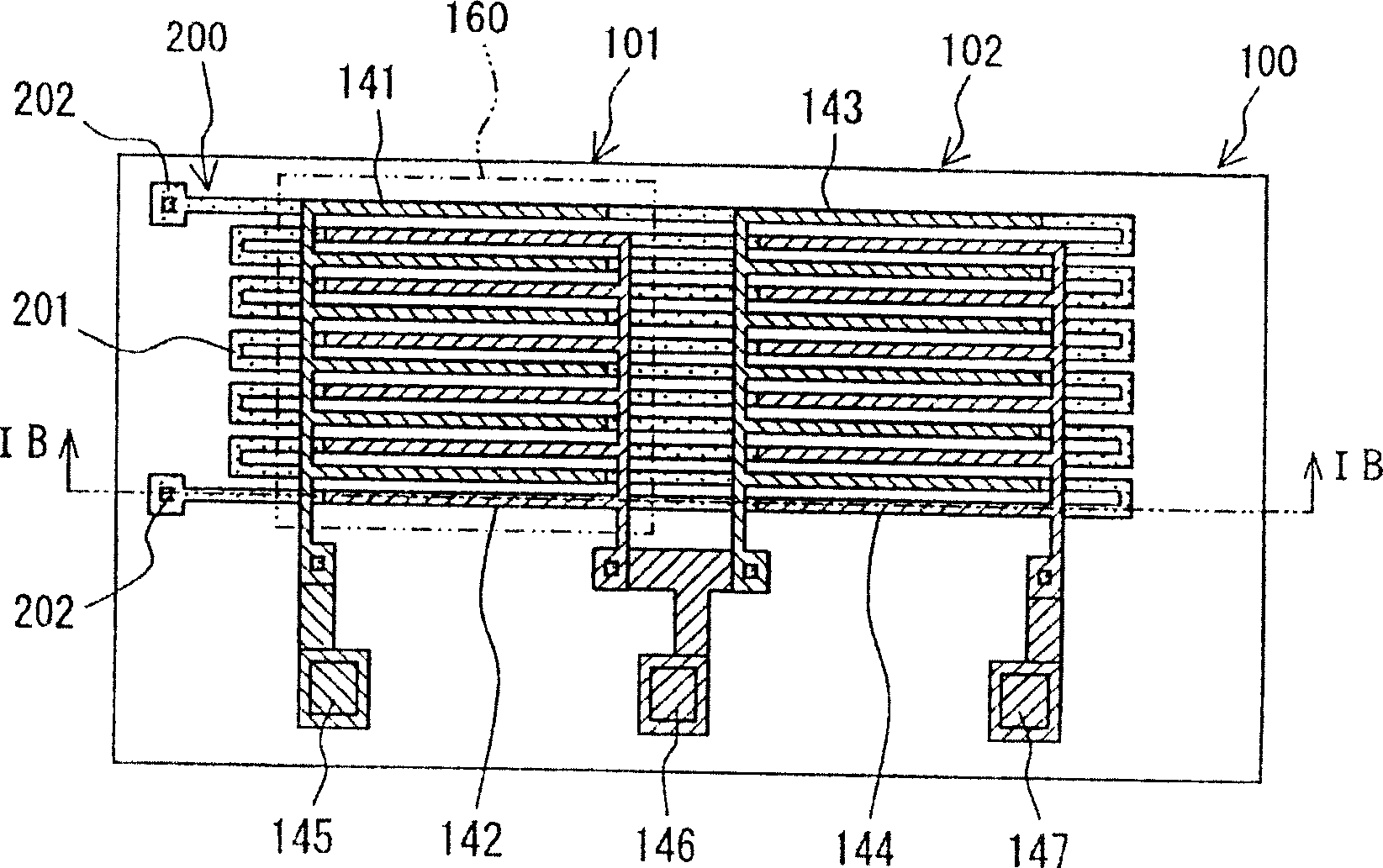
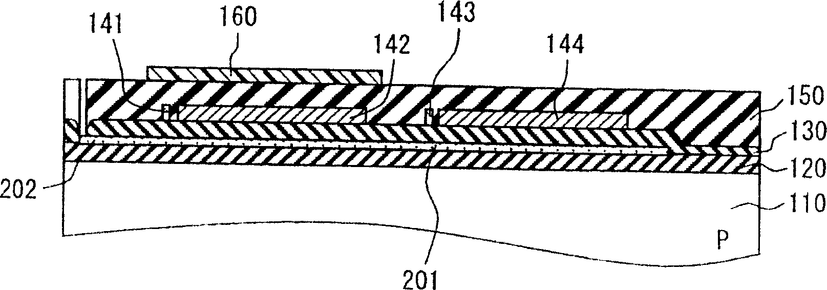
[0033] Figure 1A and 1B is an enlarged view showing a sensor portion and a heating portion of a humidity sensing device according to an embodiment, wherein Figure 1A is the floor plan, Figure 1B It is a cross-sectional view taken along 1B-1B. exist Figure 1A In , the detection electrode, reference electrode and heater electrode are shown for convenience.
[0034] Such as Figure 1A As shown, the sensor part 100 includes a detector 101 whose capacitance changes according to humidity and a reference capacitance part 102 forming a reference capacitance. Furthermore, in the present embodiment, the heater electrode 201 serving as a heating element is formed on the same substrate as the sensor portion 100 as the heating portion 200 . Reference numeral 202 denotes a pad formed at the end of the heater electrode 201 .
[0035] Such as Figure 1B As shown, reference numeral 110 denotes a semiconductor substrate as a substrate, and in this embodiment, it is formed of p-type sili...
no. 2 example
[0066] Next, we will refer to Figure 4 A second embodiment will be described. Figure 4 is an enlarged plan view showing a sensor portion and a heating portion in the humidity sensing device of this embodiment, and corresponds to that of the first embodiment. Figure 1A . For convenience, a detection electrode, a reference electrode, and a heater electrode are shown.
[0067] The humidity device of the second embodiment has many elements in common with the first embodiment. Therefore, detailed descriptions of common parts are omitted, and emphasis is placed on descriptions of different parts.
[0068] Such as Figure 4 As shown, heater electrodes 201 a , 201 b are formed on the same plane as detection electrodes 141 , 142 and reference electrodes 143 , 144 . Accordingly, when the heater electrodes 201a|, 201b are formed of the same constituent material as the detection electrodes 141, 142 and the reference electrodes 143, 144, the manufacturing process can be simplified. ...
no. 3 example
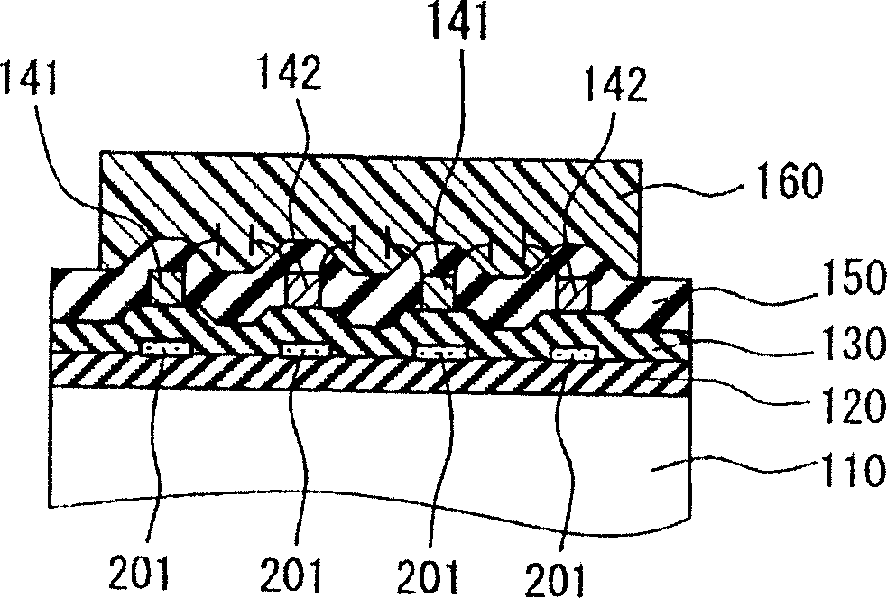
[0073] Next, refer to Figure 5 A third embodiment will be described. Figure 5 is an enlarged sectional view showing the periphery of the detector, and corresponds to that of the first embodiment Figure 2A .
[0074] The humidity sensing device of the third embodiment has many common parts with the first embodiment. Therefore, detailed descriptions of common parts are omitted, and emphasis is placed on descriptions of different parts.
[0075] Such as Figure 5 As shown, in this embodiment, the heater electrode 201a is disposed on the moisture-sensitive film 160 . With this structure, the moisture-sensing film 160 is directly heated, so that moisture in the moisture-sensing film 160 can be quickly evaporated, thereby establishing a predetermined humidity state. Therefore, the self-diagnosis time can be shortened. Since the heater electrode 201 a is provided on the moisture-sensitive film 160 , this embodiment is configured such that the heater electrode 201 a is shared...
PUM
 Abstract
Description
Claims
Application Information
 - R&D
- Intellectual Property
- Life Sciences
- Materials
- Tech Scout
- Unparalleled Data Quality
- Higher Quality Content
- 60% Fewer Hallucinations
Browse by: Latest US Patents, China's latest patents, Technical Efficacy Thesaurus, Application Domain, Technology Topic, Popular Technical Reports.
© 2025 PatSnap. All rights reserved.Legal|Privacy policy|Modern Slavery Act Transparency Statement|Sitemap|About US| Contact US: help@patsnap.com