
Organic electroluminesent panel

An electroluminescent, organic technology, applied in the field of organic electroluminescent panels, can solve problems such as peeling, strong mechanical stress, and easy corrosion

Active Publication Date: 2006-08-30
AU OPTRONICS CORP
View PDF0 Cites 6 Cited by
  • Summary
  • Abstract
  • Description
  • Claims
  • Application Information

AI Technical Summary

Problems solved by technology

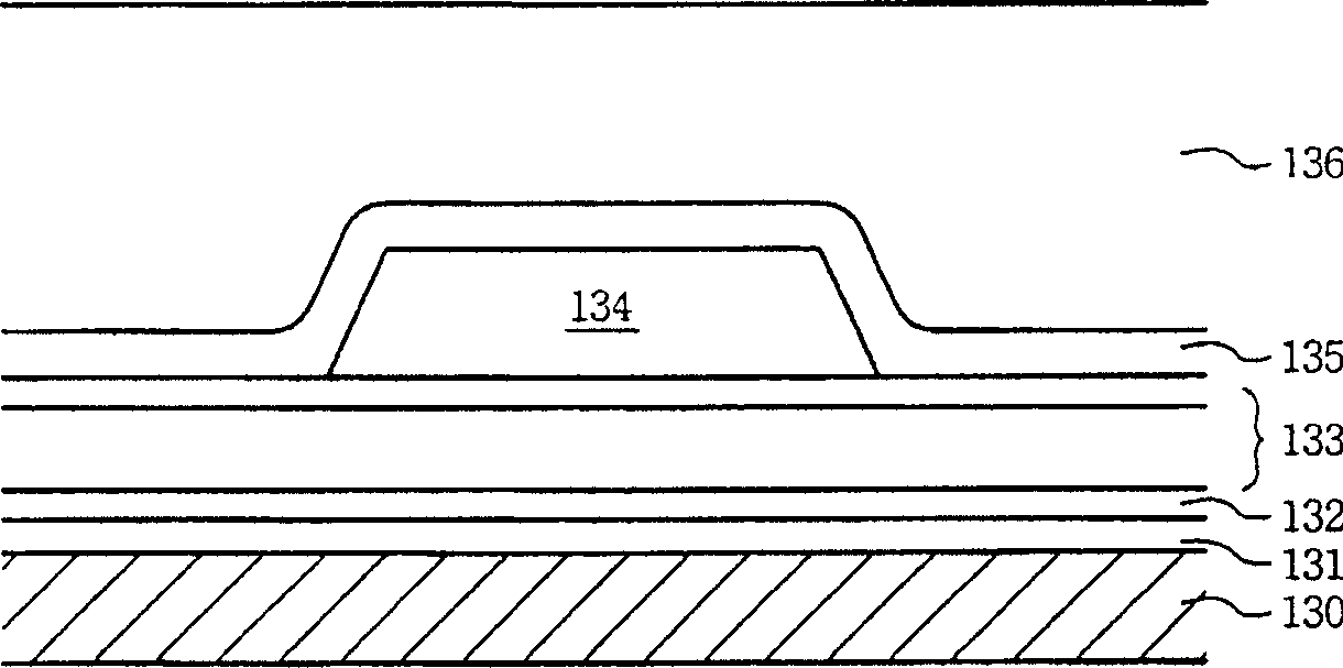
[0009] However, although thickening the metal wire can solve the above problems, it also causes the following problems: 1. Increase the process time and cost of physical vapor deposition (PVD) and etching processes; ) and the protective layer 135, which have more requirements on the step coverage (Step Coverage) capability of the post-process, or need to use a planarization process; 3. Due to the increase in thickness, the sidewall of the metal layer 134 is not completely covered by the post-process and exposed More, prone to corrosion; 4. Strong mechanical stress, prone to peeling problems

Method used


Image

  • Organic electroluminesent panel
  • Organic electroluminesent panel
  • Organic electroluminesent panel

Examples


Embodiment Construction

[0044] The organic electroluminescence panel of the present invention will be described in detail with reference to the diagrams, and preferred embodiments will be listed for illustration.

[0045] Please refer to figure 2 , is the top view of the appearance of the organic electroluminescence panel of the present invention. The organic electroluminescence panel 200 has a first substrate 210 and a second substrate 220 . There is an adhesive area 230 between the first substrate 210 and the second substrate 220 for the two substrates 210 and 220 to be pasted together. figure 2 The first substrate 210 is located below the second substrate 220 and overlapped with a flexible circuit board 240 . The second substrate 220 can serve as a packaging cover to protect the circuit structure on the first substrate 210 .

[0046] Please refer to image 3 , is a B-B sectional view of the organic electroluminescence panel 200 . A first conductive layer 212 and a pixel array 214 are dispos...


PUM


Abstract

The invention is an organic electroluminescence panel with two opposite substrates, where the first substrate is provided with a first conductive layer and a pixel array, the second substrate is arranged on the pixel array and the bottom surface of the second substrate is provided with a second conductive layer, the pixel array comprises plural organic luminous diodes connected with the first conductive layer, the second conductive layer is connected to the first conductive layer and connected through the first conductive layer to a voltage source.

Description

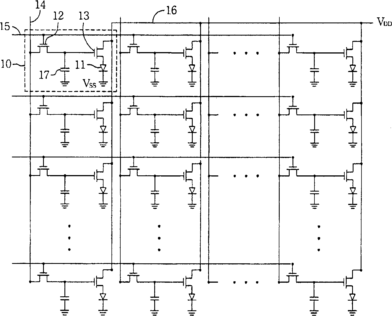
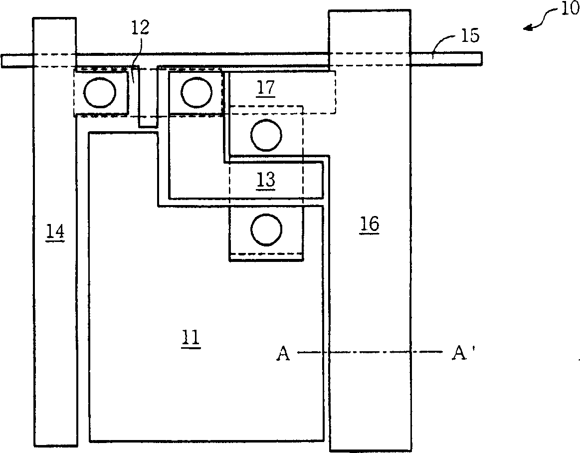
technical field [0001] The invention relates to an organic electroluminescence panel, in particular to an organic electroluminescence panel with a uniform driving current. Background technique [0002] Organic electroluminescent panels use organic light-emitting diodes as light-emitting elements. The organic light emitting diode is a current-driven element, and its luminous brightness changes with the current passing through the organic light emitting diode. Therefore, precise control of the current passing through the OLED is an important issue in the development of organic electroluminescent panels. [0003] Please refer to Figure 1A-1B , Figure 1A It is a circuit diagram of a pixel array of an existing active organic electroluminescence panel, Figure 1B for Figure 1A The floor plan of any pixel in . Each pixel 10 includes an organic light emitting diode 11, a switching transistor 12, a driving transistor 13, a data line 14, a scanning line 15, a power line 16 and...

Claims


Application Information

Patent Timeline
Patent Type & Authority Applications(China)
IPC IPC(8): H01L27/32H05B33/12
Inventor 李信宏吴冠龙
Owner AU OPTRONICS CORP
Learn More