Microphone circuit and hand-held microphone comprising same

A technology for microphones and condenser microphones, applied in transducer circuits, electrical components, sensors, etc., can solve the problems of increased cost, expensive materials, complex structure of condenser microphones, etc., and achieve the effect of reducing power consumption

Inactive Publication Date: 2006-08-30
L&LP有限公司
View PDF0 Cites 5 Cited by
  • Summary
  • Abstract
  • Description
  • Claims
  • Application Information

AI Technical Summary

Problems solved by technology

The structure of the condenser microphone is also relatively complicated, and the production and assembly are time-consuming and waste materials, which leads to an increase in cost

Method used


Image

  • Microphone circuit and hand-held microphone comprising same
  • Microphone circuit and hand-held microphone comprising same
  • Microphone circuit and hand-held microphone comprising same

Examples


Embodiment Construction

[0035] Hereinafter, the present invention will be described in detail.

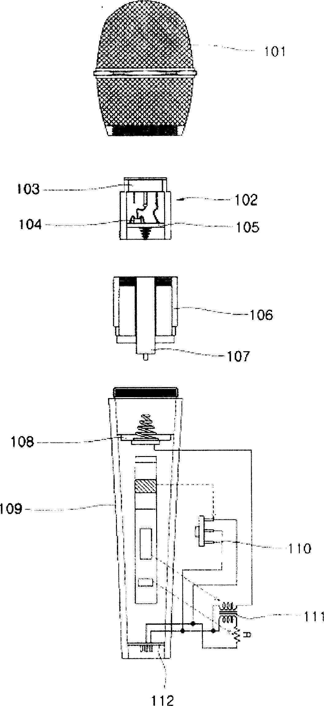
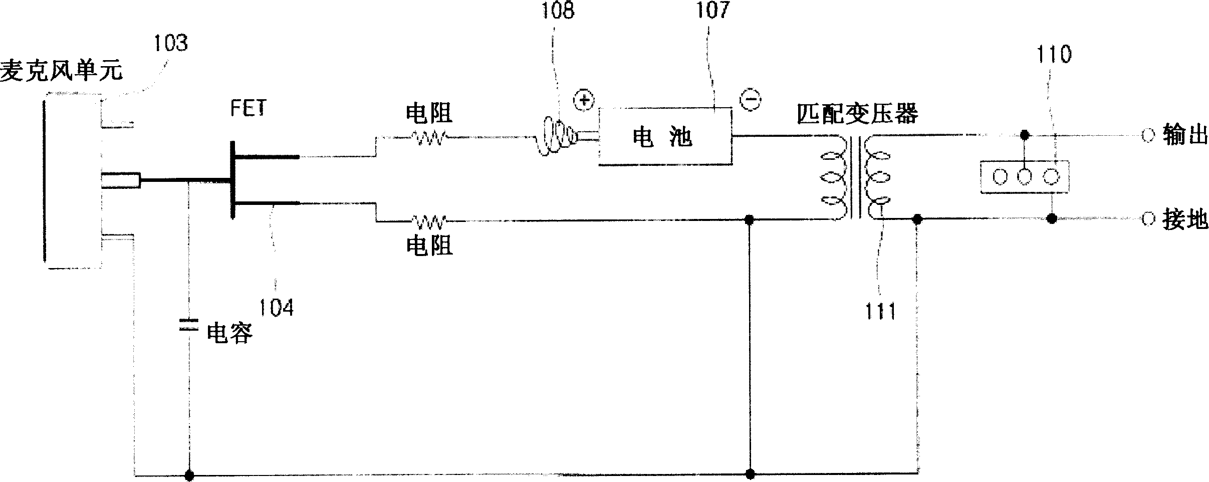
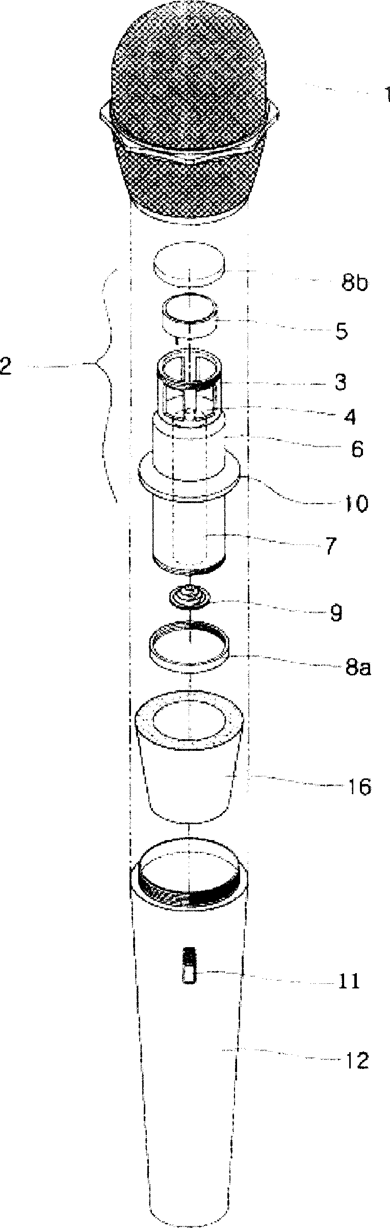
[0036] image 3 , Figure 4 It is a schematic diagram of a hand-held microphone equipped with a capacitive microphone circuit in the present invention. The microphone handle part 12 is in the shape of a tapered cylinder with different diameters at both ends, and various parts are installed in the open internal space in the length direction. A thread for screwing with the microphone cover 1 is formed on the outer surface of one end of the microphone handle portion 12 .

[0037] In addition, the battery 7 that supplies power to the microphone circuit is controlled by a power switch 11. A part of the power switch 11 is exposed outside the microphone handle part 12, and in order to carry out a wired connection with an unshown audio-visual device, the internal space of the microphone handle part 12 One end is provided with interface 13.

[0038] In addition, when the capacitive microphone assembly 6 is combin...


PUM


Abstract

The invention sets delay circuit part between battery and FET, to switch the capacitor microphone to connect / cutoff state, to avoid the sound caused by broken circuit current or instant current; uses transistor to cutoff circuit; therefore, when the microphone is in closed state, it can broke the current fully; at the invention mounts other elements of microphone circuit as battery, to reduce the element number of microphone, to simplify the production process, and improve the interchangeability with dynamic microphone.

Description

technical field [0001] The invention relates to a microphone circuit and a hand-held microphone including the circuit, in particular, it can avoid the "click" sound caused by the inrush current or the circuit breaker current when the microphone is turned on and off, and there is no current when the microphone is kept in the off state, while trying to A microphone circuit that reduces the number of parts, simplifies the production and assembly process of the microphone, and improves the interchangeability between dynamic handy microphones (Dynamic Handy Microphone), and uses a hand-held microphone including the microphone circuit. Background technique [0002] Existing microphones include dynamic microphones and condenser microphones (Condenser Microphone). The above-mentioned dynamic microphone utilizes the principle that an electromotive force is generated when a conductor moves in a magnetic field, and can be divided into a ribbon microphone and a dynamic microphone accord...

Claims


Application Information

Patent Timeline
Patent Type & Authority Applications(China)
IPC IPC(8): H04R3/00
Inventor 李重国
Owner L&LP有限公司
Why Eureka
Try Eureka