Engine starter designed to have enhanced stability of engagement of pinion with ring gear

A pinion, engine technology, used in the field of starters

Inactive Publication Date: 2006-09-06
DENSO CORP
View PDF1 Cites 8 Cited by
  • Summary
  • Abstract
  • Description
  • Claims
  • Application Information

AI Technical Summary

Problems solved by technology

But the idle-stop system requires multiple re-uses of the starter and has problems with the large pinion and ring gear failing engagement prematurely

Method used


Image

  • Engine starter designed to have enhanced stability of engagement of pinion with ring gear
  • Engine starter designed to have enhanced stability of engagement of pinion with ring gear
  • Engine starter designed to have enhanced stability of engagement of pinion with ring gear

Examples


Embodiment Construction

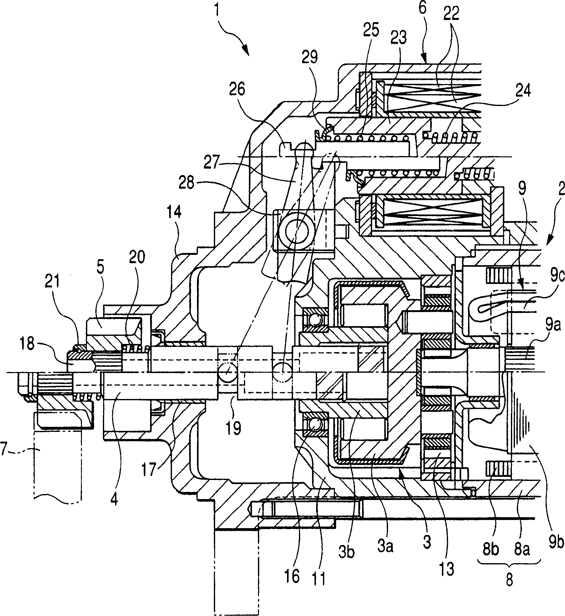
[0022] Referring to the drawings, in which like reference numerals refer to like parts throughout the several views, in particular figure 1 , denotes a starter 1 according to a first embodiment of the present invention that can be used to start a vehicle engine.

[0023] The starter 1 mainly includes a housing 10 , an electric motor 2 , a speed reducer (described in detail below), a clutch 3 , a pinion shaft 4 , a pinion 5 and an electromagnetic switch 6 . The speed reducer is used to reduce the output speed of the motor 2 and transmit it to the pinion shaft 4 via the clutch 3 . The pinion shaft 4 has a pinion 5 mounted thereon. The electromagnetic switch 6 is used to close a main contact (not shown) installed in the drive circuit of the motor 2, and advance the pinion shaft 4 in its axial direction. exist figure 1 In , the upper side above the longitudinal centerline of the pinion shaft 4 represents the starter 1 in a stationary state, while the lower side represents the...


PUM


Abstract

A starter for automotive engines is provided which is equipped with a pinion carrier which is shifted by a magnetic attraction, as transmitted from a solenoid switch through a shift lever, to establish engagement of a pinion with a ring gear jointed to the engine. If thrust acting on the pinion carrier to urge the pinion against the ring gear through when the pinion has been shifted and hit the ring gear, so that the pinion is placed in abutment with the ring gear is defined as N (Newton), and the mass of the pinion carrier is defined as g (gram), a relation of g / N<=6 is met. This improves the ability of engagement of the pinion with the ring gear, thus resulting in an increased life span of the starter.

Description

technical field [0001] The present invention relates generally to a starter for starting a vehicle engine, and more particularly to an improved structure of such a starter equipped with a pinion carrier that passes a magnetic attraction transmitted from an electromagnetic switch via a moving rod. and move so that the pinion and the ring gear connected to the engine come into engagement. Background technique [0002] Japanese Utility Model First Publication No. 2-87967 discloses a typical engine starter equipped with an output shaft to which the torque of an electric motor is transmitted, a pinion to which torque is transmitted from the output shaft via a clutch and a magnetic switch to turn the motor on or off. When the electromagnetic switch is activated, a magnetic attraction is formed to attract the plunger, and this movement of the plunger is transmitted to the clutch through the moving rod to move the pinion along the output shaft and the clutch, so that the pinion and...

Claims


Application Information

Patent Timeline
Patent Type & Authority Applications(China)
IPC IPC(8): F02N11/00
CPCF02N15/046F02N11/0851F02N2300/104F02N15/023F02N15/067Y10T74/13H01B1/02H01B3/30H01B7/17
Inventor 梶野定义长谷川洋一
Owner DENSO CORP
Why Eureka
Try Eureka