Substrate processing device, method and program

A technology of a substrate processing device and a substrate processing method, which is applied to the device for coating liquid on the surface, physical therapy, transportation and packaging, etc., can solve problems such as difficulty in shortening the intermittent time, and achieve the effect of shortening the intermittent time

Active Publication Date: 2006-09-06
TOKYO ELECTRON LTD
View PDF1 Cites 18 Cited by
  • Summary
  • Abstract
  • Description
  • Claims
  • Application Information

AI Technical Summary

Problems solved by technology

Therefore, there is a problem that, in addition to the time required for scanning the resist nozzle (Tc), the time required for carrying or loading the unprocessed substrate on the stage (Tin), The time required for one coating process (Tc+Tin+Tout) obtained from the time required for unloading or carrying out the processed substrate from the stage (Tout) is the tact time (tact time) as it is. , making it difficult to shorten the intermittent time
[0006] Moreover, there is also a problem that it is difficult to keep such a thick and long resist nozzle under load constantly because the size and weight of the long resist nozzle increase with the increase in substrate size. The predetermined height position (narrow gap) above the object stage remains unchanged and it moves stably horizontally at a certain speed

Method used


Image

  • Substrate processing device, method and program
  • Substrate processing device, method and program
  • Substrate processing device, method and program

Examples


Embodiment Construction

[0072] Hereinafter, preferred embodiments of the present invention will be described with reference to the drawings.

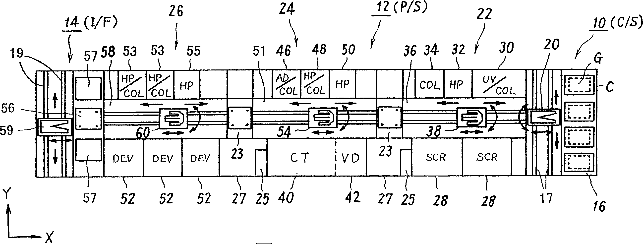
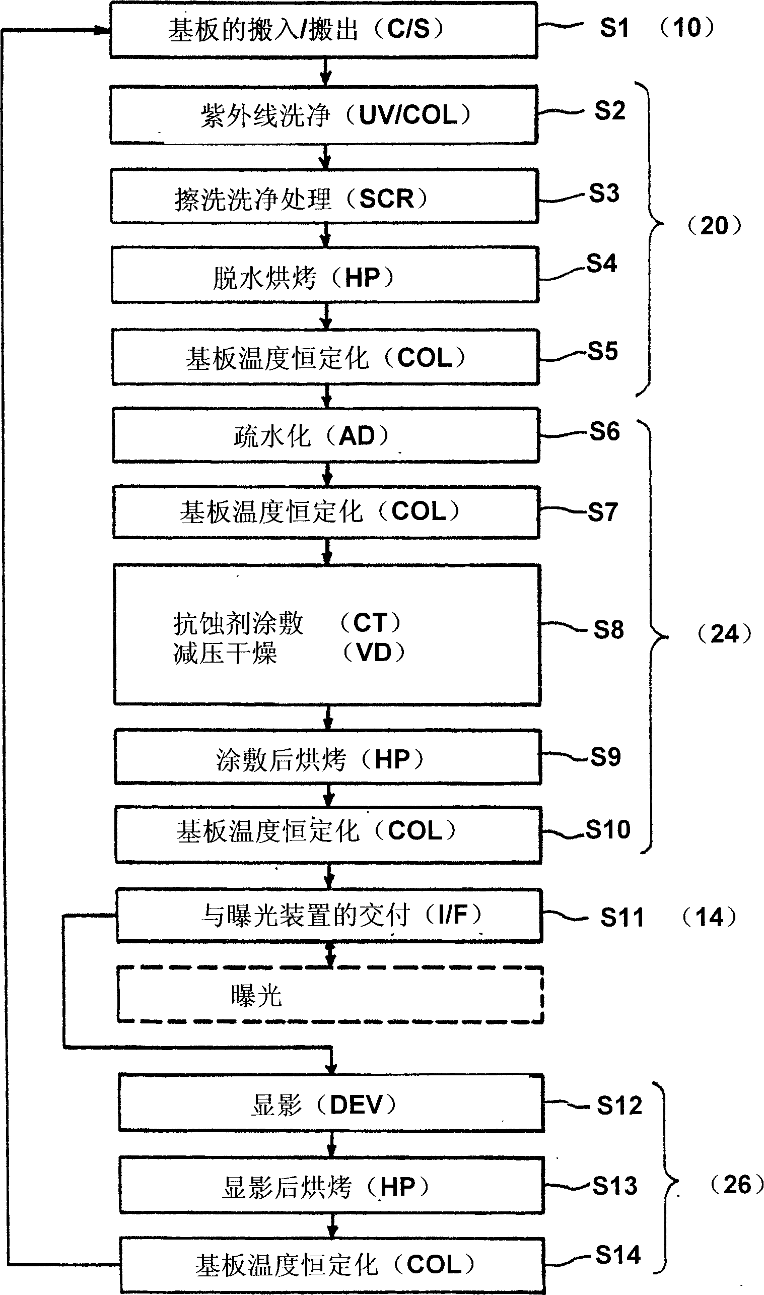
[0073] figure 1 It shows an example of a configuration that a coating and development processing system can be applied to as the substrate processing apparatus of the present invention. The coating and development processing system is installed in a clean room, for example, the LCD substrate is used as the substrate to be processed. In the LCD manufacturing process, cleaning, resist coating, pre-baking, developing and post-baking are performed in the photolithography process. each processing.

[0074] Roughly speaking, this coating and development processing system is composed of a cassette station (C / S) 10 , a processing station (P / S) 12 and an interface unit (I / F) 14 .

[0075] The box station (C / S) 10 provided on one end of the system includes: a box loading station 16, which can place a predetermined number (for example, 4) of boxes C containing a plural...


PUM


Abstract

This invention provides a base plate treating apparatus. The conveying parts (84A, 84B) of the first and the second base plate hold base plate (G) conveying interval, and the conveying interval refers to the interval from the coating starting position to the coating ending position instead of the total conveying interval from in-position to out-position. The first base plate conveying part (84A) conveys base plate (G [i]) to the coating ending position and returns to the in-position directly, then the base plate conveying part (84A) begins to convey the subsequent new base plate (G [i+1]). While the second base plate conveying parts (84B) conveys the base plate (G [i]) from the coating ending position to the out-position by itself, then the conveying parts (84B) returns to the coating starting position and waits for the arrival of next base plate (G [i+1]) conveyed by the first base plate conveying part (84A) itself. This invention can greatly shorten the intermittent time of supplying treatment fluid to the dealing base plate without rotation mode.

Description

technical field [0001] The present invention relates to the technology of supplying and processing the processing liquid on the substrate to be processed, and particularly relates to the substrate processing technology of coating the processing liquid on the substrate in a non-rotational manner. Background technique [0002] At present, in the photolithography (photolithograph) process in the flat panel display (FPD) manufacturing process, as a resist coating method that is conducive to increasing the size of the substrate (such as a glass substrate) to be processed, it is widely used. The long resist nozzle sprays the resist liquid on the substrate in a strip shape, and the resist liquid is coated on the substrate without rotational movement by scanning the resist nozzle relatively on one side. Rotation-free method for desired film thickness. [0003] According to the conventional resist coating apparatus of the non-rotation method, for example, as described in Patent Docu...

Claims


Application Information

Patent Timeline
Patent Type & Authority Applications(China)
IPC IPC(8): H01L21/00H01L21/677B05C5/02
CPCA61H23/0218A61H2201/0153A61H2201/0169A61H2201/169
Inventor 大塚庆崇中满孝志
Owner TOKYO ELECTRON LTD
Why Eureka
Try Eureka