Protection means used for calcination starting or preheating exchanging inert anode for electrolysis of aluminium
A technology of inert anodes and protection devices, applied in the field of inert anodes, can solve problems such as non-damage replacement
- Summary
- Abstract
- Description
- Claims
- Application Information
AI Technical Summary
Problems solved by technology
Method used
Image


Examples
Embodiment 1
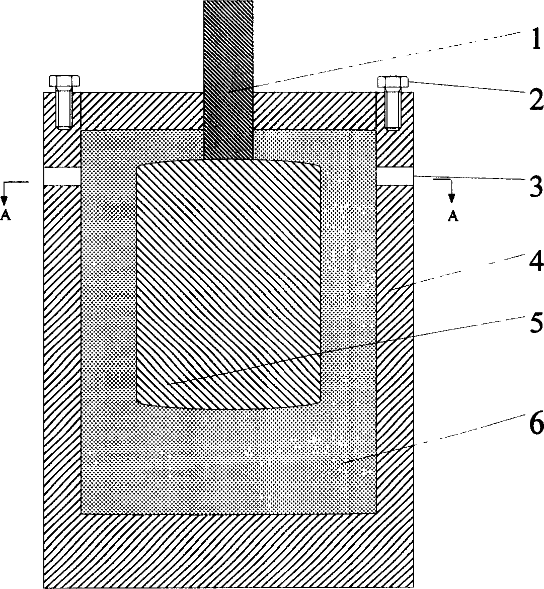
[0030] Such as figure 1 , depicting the schematic structure of a protective device for cylindrical or cup-shaped inert anodes. It mainly includes an anode guide rod 1, a conductive terminal 2, a suspension hole 3, a cylindrical or rectangular parallelepiped anode protective tank body 4, an inert anode 5, and a filling material 6. The tank body 4 of the anode protection device has a cylindrical structure, and the tank body and end caps can be made of graphite, petroleum coke, coke, etc., or a mixture thereof. The conductive terminal 2 is made of steel or carbonaceous material and is tightly connected with the end cover by means of mechanical or bonding. The working surface of the tank body is the bottom of the tank body, and its thickness is larger than that of the tank wall, generally 3 to 20 times the thickness of the tank wall. In addition to the space for anodes, a space of 5-50mm is reserved on the top, bottom, left, and right sides of the tank for filling material space...
Embodiment 2
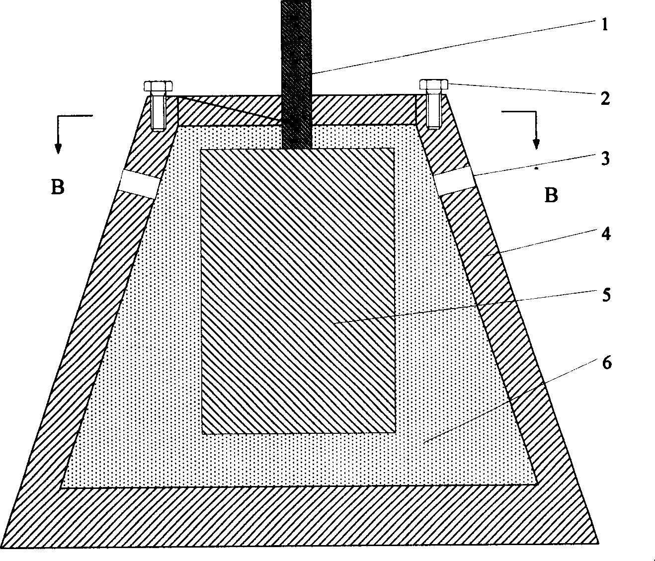
[0032] image 3 It is a schematic diagram of the structure of an inert anode protection device with a frustum of cone structure, Figure 5 It is a structural schematic diagram of an inert anode protection device with a multi-step structure, including an anode guide rod 1, a conductive terminal 2, a suspension hole 3, a frustum or multi-step type anode protection device tank 4, an inert anode 5, and a filling material 6. The tank structure of this type of anode protection device adopts a cone or multi-step design, the top is small and the bottom is large, and the bottom of the tank is specially thickened, so it is especially suitable for the firing start-up of aluminum electrolytic cells. The materials used and the operation method of the protective device are the same as those in Example 1. Due to its large size and weight, holes are drilled in the tank body and a suspension mechanism is added.
Embodiment 3
[0034] Figure 7 The schematic structure of flat and disc-shaped inert anode protection devices is described. It mainly includes an anode guide rod 1, a conductive terminal 2, a suspension hole 3, a plate-shaped or sheet-shaped inert anode protection device tank 4, an inert anode 5, and a filling material 6. The materials used and the operation method of the protective device are the same as those in Example 1. Since the plate-shaped or sheet-shaped inert anode uses the side as the working surface, the side of the tank of the anode protection device adopts a thickened design and adds a suspension and lead-out mechanism to ensure the needs of use.
PUM
| Property | Measurement | Unit |
|---|---|---|
| thickness | aaaaa | aaaaa |
Abstract
Description
Claims
Application Information
 - R&D
- Intellectual Property
- Life Sciences
- Materials
- Tech Scout
- Unparalleled Data Quality
- Higher Quality Content
- 60% Fewer Hallucinations
Browse by: Latest US Patents, China's latest patents, Technical Efficacy Thesaurus, Application Domain, Technology Topic, Popular Technical Reports.
© 2025 PatSnap. All rights reserved.Legal|Privacy policy|Modern Slavery Act Transparency Statement|Sitemap|About US| Contact US: help@patsnap.com