Electroplating apparatus

An electroplating device and electroplating technology, which is applied to circuits, electrical components, electrolytic processes, etc., can solve problems such as uneven screw fastening pressure and deterioration of sealing performance

Active Publication Date: 2006-09-13
YAMAMOTO MS
View PDF1 Cites 4 Cited by
  • Summary
  • Abstract
  • Description
  • Claims
  • Application Information

AI Technical Summary

Problems solved by technology

However, since larger plating units require more screws, the tightening pressure on these screws becomes more uneven
As a result, the sealing performance of the first O-ring 104 and the second O-ring 105 is further deteriorated

Method used


Image

  • Electroplating apparatus
  • Electroplating apparatus
  • Electroplating apparatus

Examples


Embodiment Construction

[0026] Embodiments of the present invention will be described in detail herein, referring to the accompanying drawings as necessary.

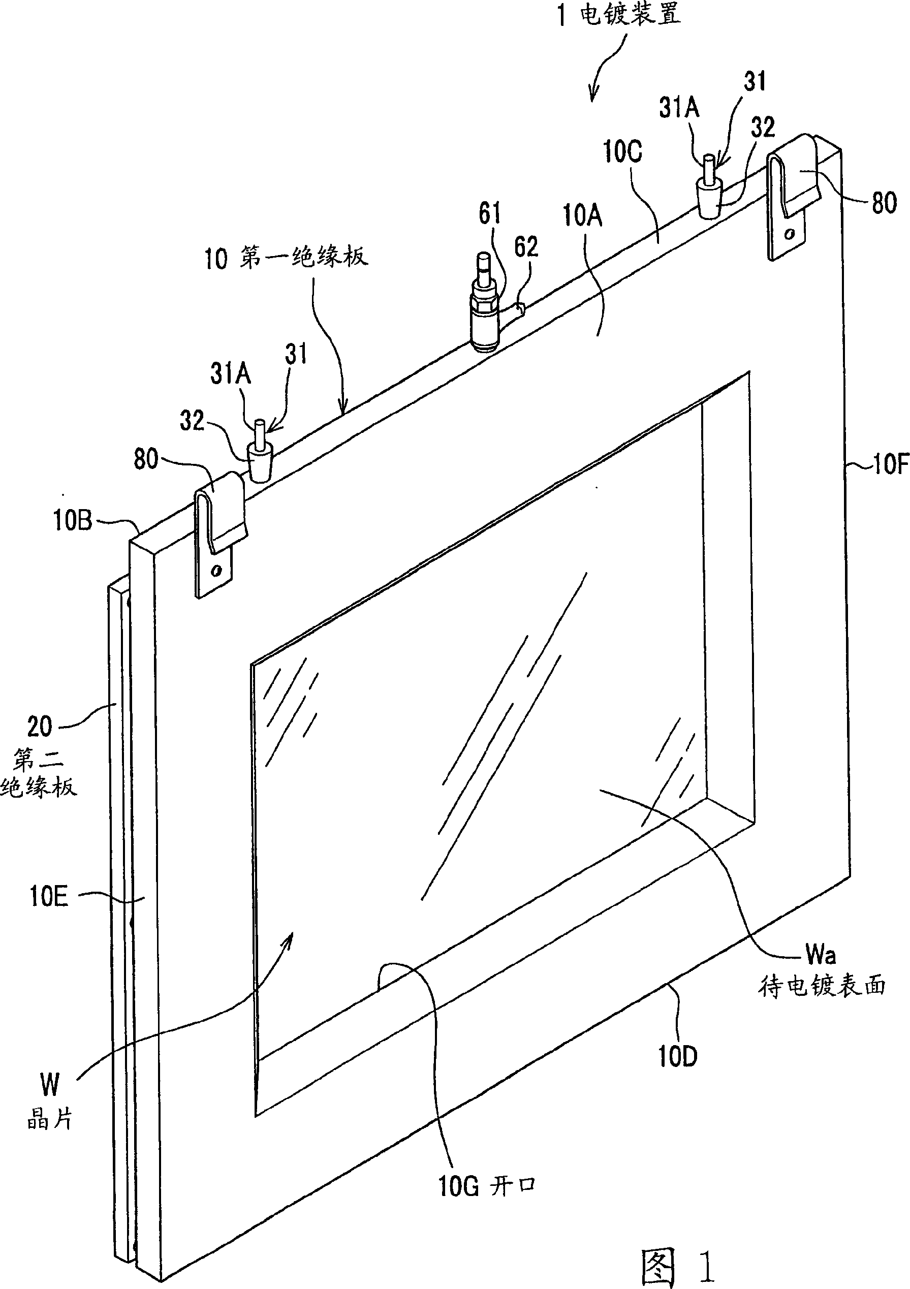
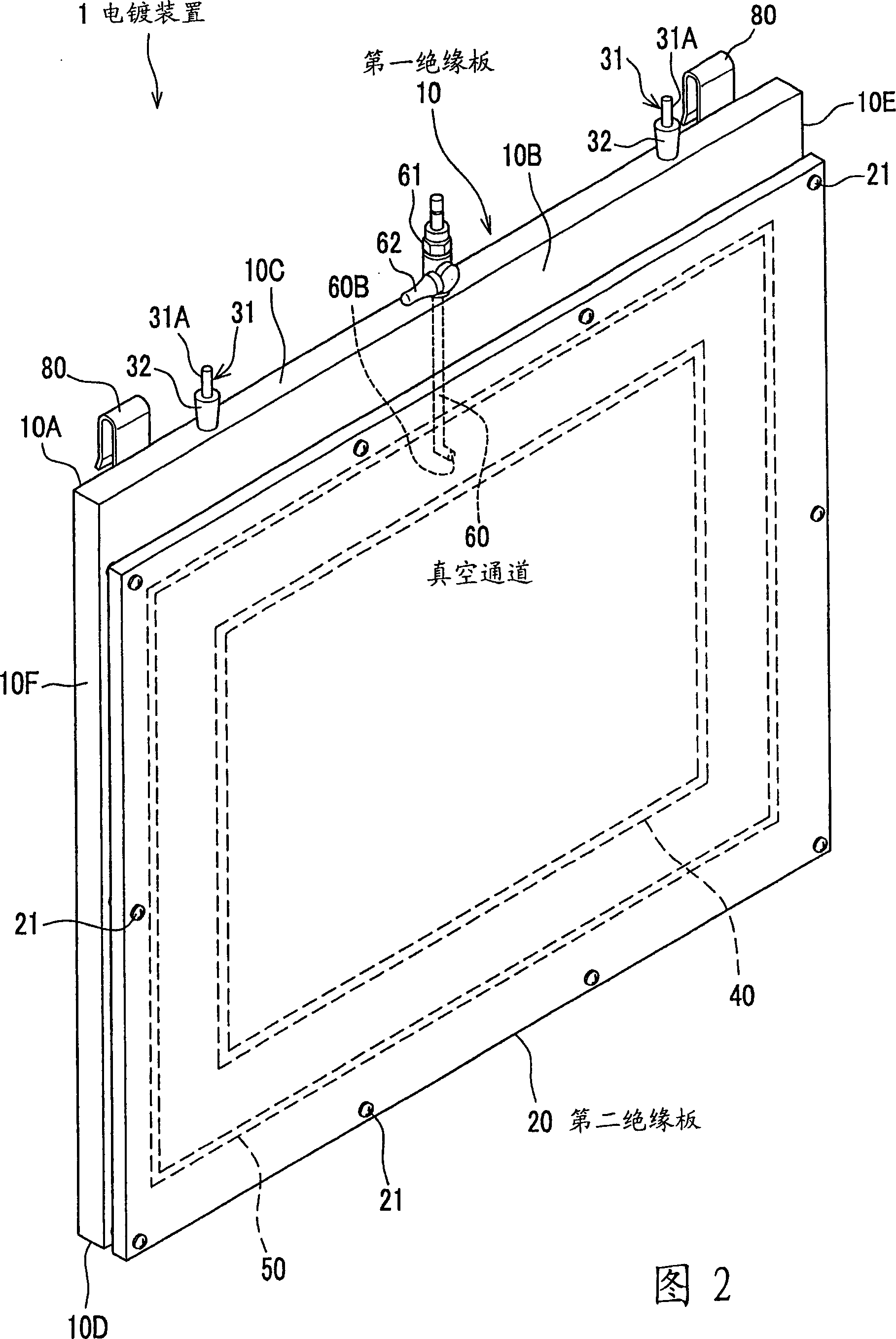
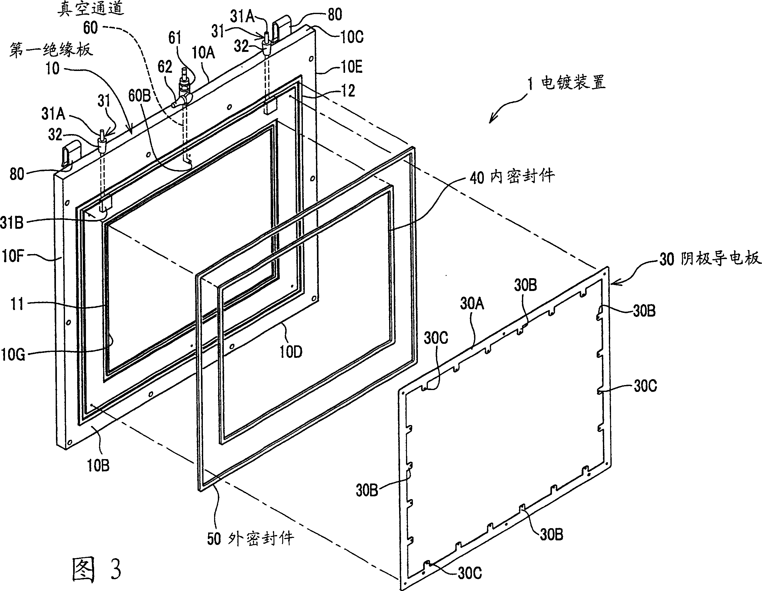
[0027] Figure 1 to Figure 4 As shown, the electroplating device 1 generally includes: a first insulating plate 10 , a second insulating plate 20 , a cathode conductive plate (conductor) 30 for conducting current, an inner seal 40 , an outer seal 50 and a vacuum channel 60 .

[0028] The first insulating plate 10 is, for example, a flat plate made of an insulating material such as an acryl plate, and is formed in a substantially rectangular shape. As shown in FIGS. 1 and 2 , the first insulating plate 10 has a front surface 10A, a rear surface 10B, a top surface 10C, a bottom surface 10D, a left side 10E, and a right side 10F. An opening 10G having a substantially rectangular shape is formed in the first insulating plate 10 . A surface Wa to be plated of a wafer W (described later) is exposed through the opening 10G. Further, as shown in FIG....


PUM


Abstract

An electroplating apparatus including a first insulated plate which has an opening, a second insulated plate which holds an object to be electroplated between the first insulated plate and the second insulated plate in such a way that the object to be electroplated is exposed through the opening, an inner seal which is provided around a periphery of the opening between the first insulated plate and the object to be electroplated, a conductor which is provided between the first insulated plate and the second insulated plate surrounding the object to be electroplated so as to conduct electricity to the object to be electroplated, and an outer seal which is provided between the first insulated plate and the second insulated plate surrounding the conductor, in which a vacuum passage is formed inside the first insulated plate and / or the second insulated plate in order to make and keep air pressure in a space surrounded by the first insulated plate, the second insulated plate, the inner seal, and the outer seal, negative.

Description

technical field [0001] The present invention relates to an electroplating apparatus for electroplating and anodizing on surfaces such as wafers, glass substrates and ceramic substrates. Background technique [0002] In recent years, plating technology has been applied to various technical fields including wiring technology in semiconductors. In the field of semiconductors, reduction in wiring pitch is required to achieve high integration and high performance. For example, in the wiring technology adopted in recent years, an interlayer insulating film is formed, followed by a dry etching process to form wiring grooves in which wiring materials are plated and filled. [0003] In order to realize this plating technique, it is necessary to uniformly plate a wiring material in a groove formed on an object to be plated. Therefore, the present applicant has proposed a plating apparatus that can form a uniform plating film on a surface to be plated of an object to be plated (for e...

Claims


Application Information

Patent Timeline
Patent Type & Authority Applications(China)
IPC IPC(8): C25D17/00C25D7/12
CPCC25D17/06H05K2203/1147C25D17/001C25D7/12
Inventor 山本渡秋山胜德原田文男
Owner YAMAMOTO MS
Why Eureka
Try Eureka