
Power tool torque overload clutch

An overload clutch and clutch technology, which is applied in the field of power tools and torque overload clutches, can solve the problems of drive chain gearbox displacement, wear, damage height, etc.

Inactive Publication Date: 2006-09-20
BLACK & DECKER INC
View PDF2 Cites 20 Cited by
  • Summary
  • Abstract
  • Description
  • Claims
  • Application Information

AI Technical Summary

Problems solved by technology

Also, in units that operate without a clutch, the motor may stall, or components of the drive chain or gearbox may become dislodged, causing damage or high wear on themselves or other mechanisms

Method used


Image

  • Power tool torque overload clutch
  • Power tool torque overload clutch
  • Power tool torque overload clutch

Examples


Embodiment Construction

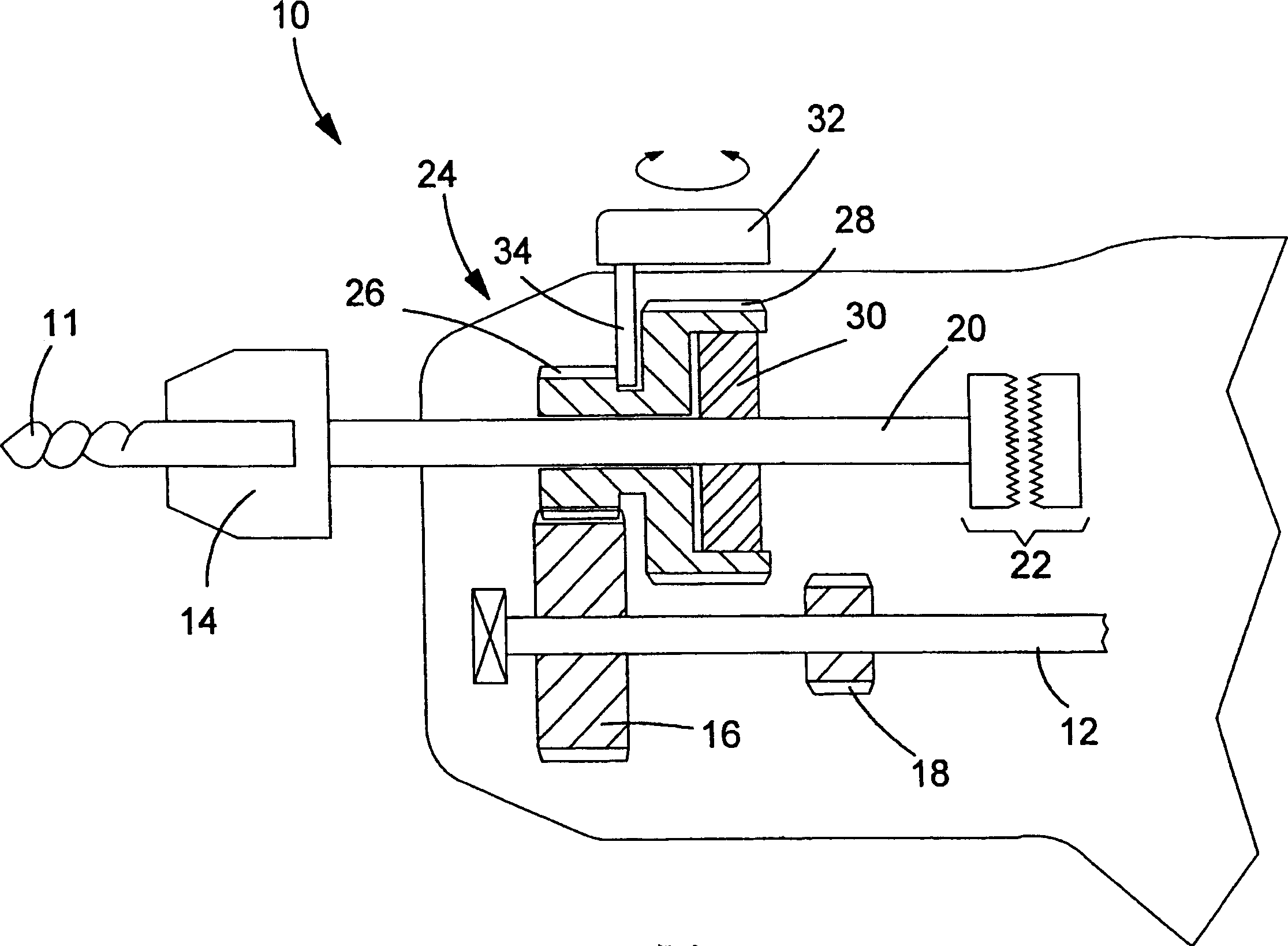
[0026] Hammer drills often have a gearbox with a transmission mechanism in it. According to the requirements of the user and / or the needs of the work in progress, the power tool can be set to output at two or more rotation speeds. Generally speaking, the clutch can be arranged on an intermediate shaft in the gearbox, which is arranged between the motor shaft and the output shaft. However, gear reduction usually affects the torque when the clutch mechanism is working. In other words, the predetermined torque when the clutch cuts in to interrupt the drive from the motor will depend on whether the drill is working at a higher or lower speed; this depends on the gear ratio used by the tool. It seems that this problem can be overcome by placing a clutch between the gearbox and the output shaft, so that the power from the motor is interrupted on the output shaft. However, the provision of a clutch mechanism on the output shaft of the hammer drill is known to cause problems, especially b...


PUM


Abstract

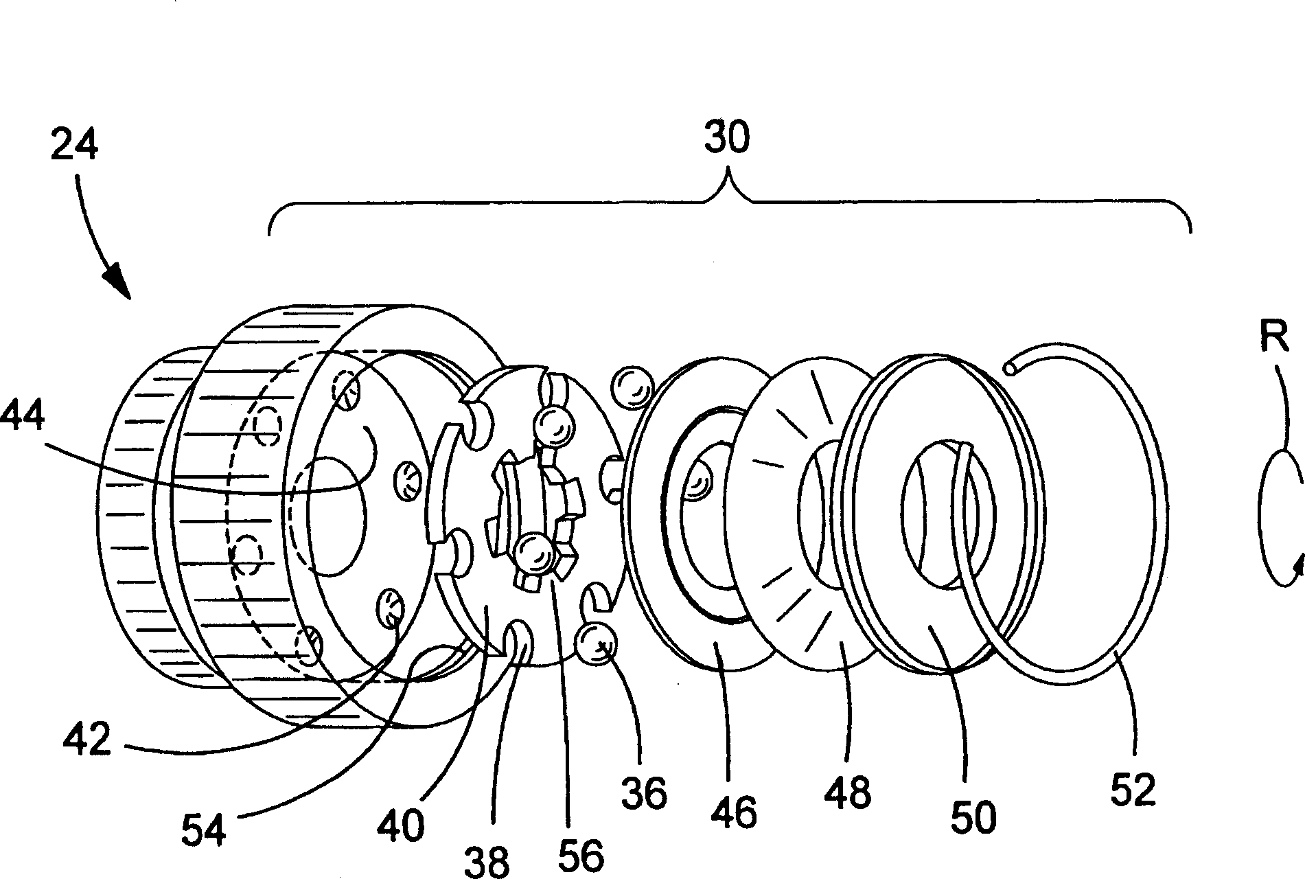
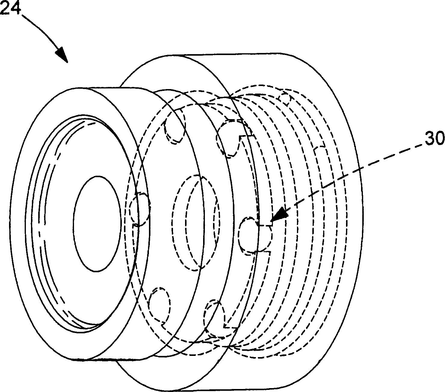
A torque overload clutch for power tools such as hammer drills. The clutch is housed in the cavity of the gear unit. Spring washers are used to push the ball bearings into indentations formed in the bottom of the cavity. Ball bearings are housed within cavities formed in a drive plate that engages the drive shaft of the power tool. The spring washers are held in place by round clips or threaded plates. A threaded plate arrangement is provided for means of compressing spring washers with a constant force through a manufacturing lot. Also disclosed is a manufacturing method of the clutch.

Description

Technical field [0001] The present invention relates to an overload clutch, and is particularly suitable for a torque overload clutch in a power tool. More specifically, the present invention relates to a torque overload clutch used in an electric hammer drill. The invention also relates to a power tool including such a clutch mechanism. [0002] The embodiments of the present invention are described below with reference to a hammer drill. However, the concept of the present invention is not limited to this device and the clutch implementing the present invention can also be used in other power tools such as circular saws or grinders. Background technique [0003] During the normal operation of the hammer drill, the drill bit rotates while the drill bit is subjected to repeated impacts. This type of drill is often used to treat masonry buildings or the like. The impact mechanism can be a pneumatic or impact type known in the art. Moreover, the hammer drill can be set to operate i...

Claims


Application Information

Patent Timeline
Patent Type & Authority Applications(China)
IPC IPC(8): B25F5/00F16D43/20F16D7/00B23Q11/04B23D47/12B24B23/02B25D9/00B25D11/10B25D16/00F16D7/08F16D43/206F16H3/30
CPCB25F5/001B25D16/006F16D7/08F16D43/206B25D9/00B25D2250/165B25D2250/321B24B23/02B25D16/003F16H3/30B25D11/106B23D47/12B23B45/008B23Q11/04F16D13/76F16H3/22
Inventor 乔纳森·阿姆斯特朗
Owner BLACK & DECKER INC
Learn More