Glassfiber-reinforced polyurethane-polyisocyanurate foam

A technology of polyisocyanurate and foam plastics, which is applied in the field of rigid polyurethane/polyisocyanurate foam plastics, and can solve problems such as hindering the detection of liquefied gas transport tanks

Active Publication Date: 2006-09-20
GAZTRANSPORT & TECHNIGAZ
View PDF2 Cites 38 Cited by
  • Summary
  • Abstract
  • Description
  • Claims
  • Application Information

AI Technical Summary

Problems solved by technology

But the latter is still a highly flammable gas
Also, the use of such hydroca

Method used

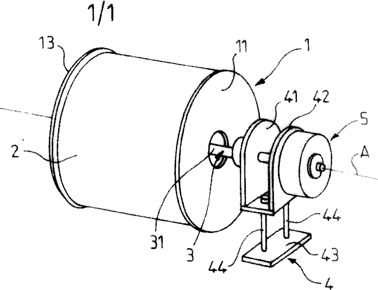
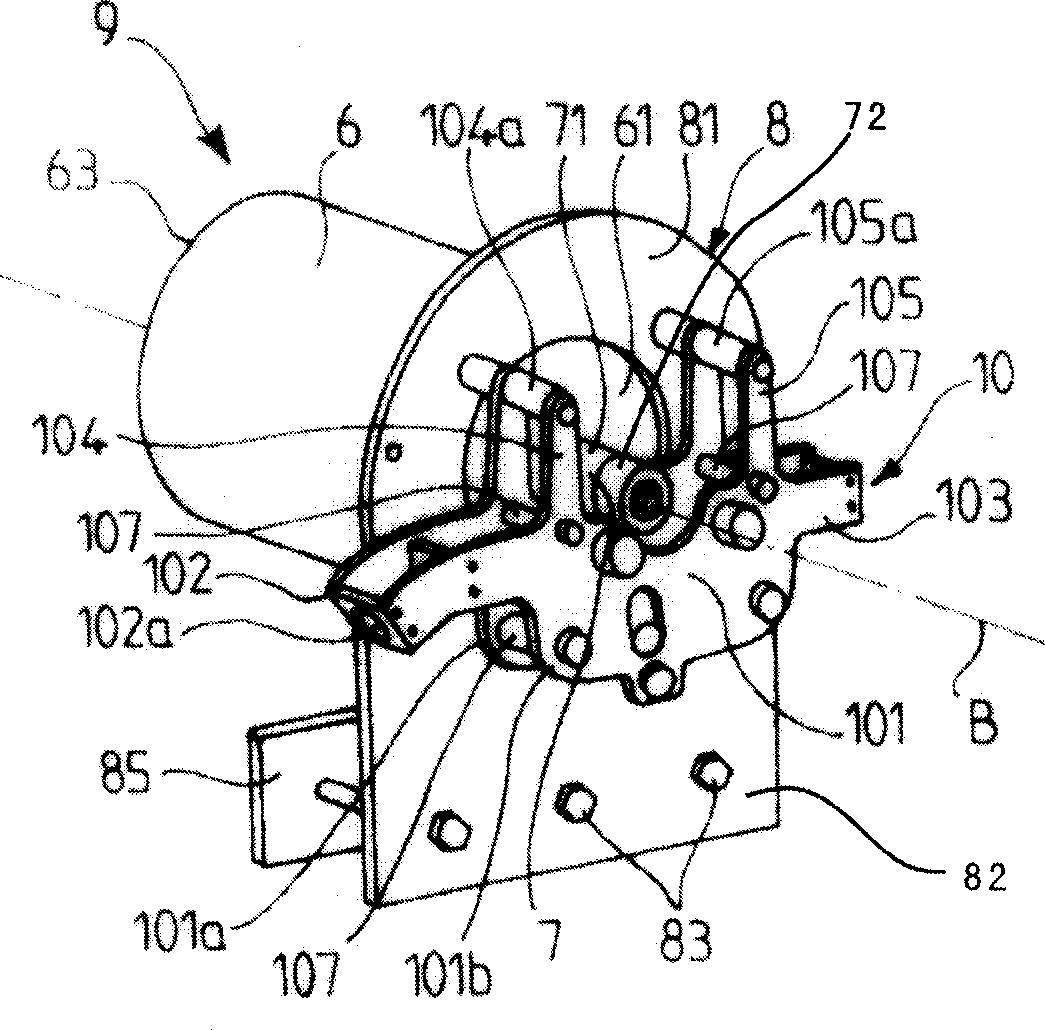
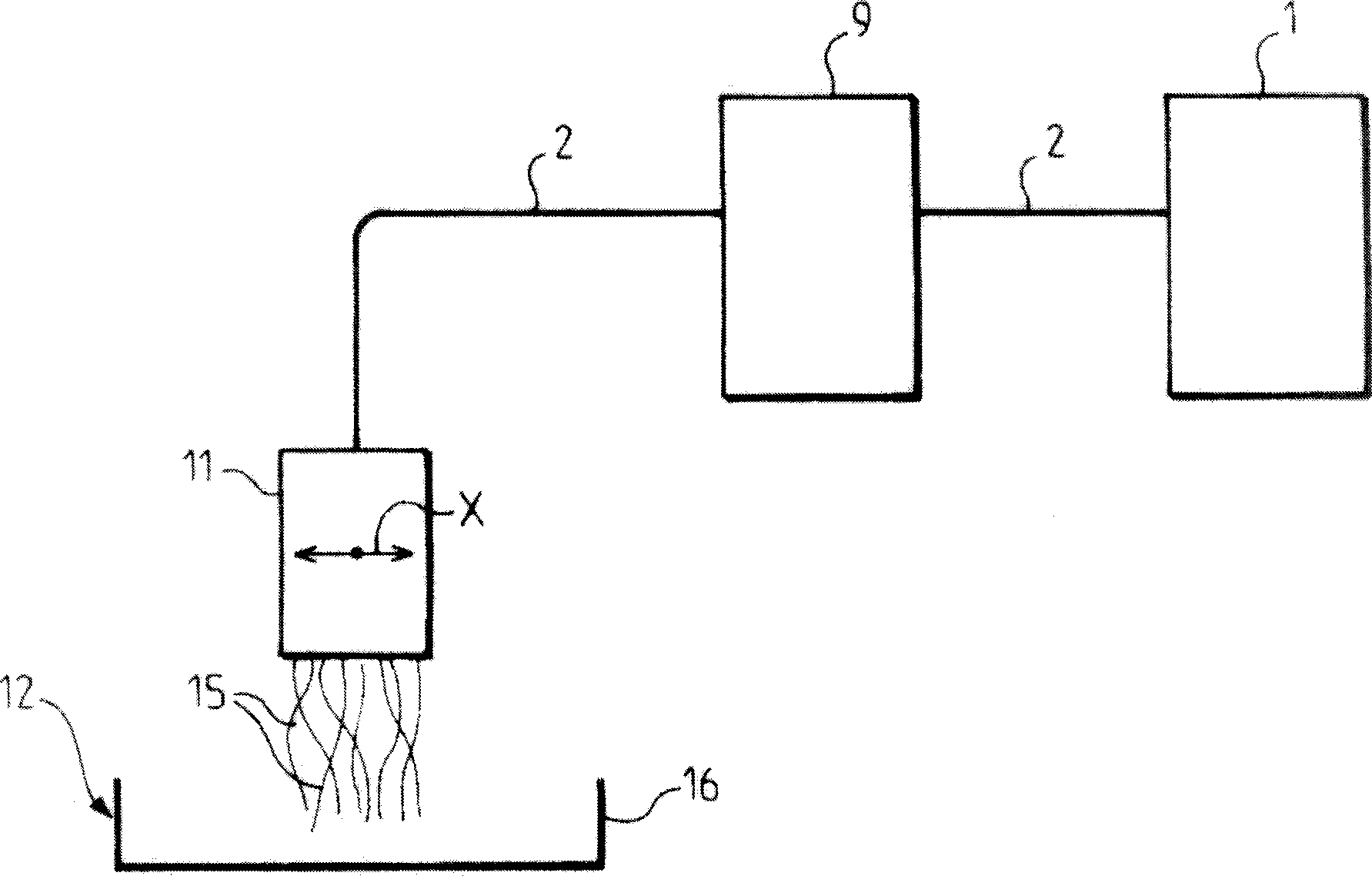

Image

  • Glassfiber-reinforced polyurethane-polyisocyanurate foam
  • Glassfiber-reinforced polyurethane-polyisocyanurate foam
  • Glassfiber-reinforced polyurethane-polyisocyanurate foam

Examples


Embodiment Construction

[0063] According to the present invention, PUIR foams are formed by the reaction between the isocyanate component and the polyol component which consists of a polyol mixture. The reaction between these different compounds proceeds according to the following four steps:

[0064]

[0065] response 2

[0066] Response 3

[0067] response 4

[0068] The first step, the initiation step, is the one in which water molecules react with the -NCO groups of the isocyanate component to form amine groups and CO2 molecules. The release of CO2 causes the foam to expand.

[0069] In the second step, the amine group obtained from the first step is reacted with an -NCO group to form a urea group.

[0070] In parallel, in a third step, the hydroxyl groups of the polyol component react with -NCO groups to form urethane groups.

[0071] Finally, in the fourth step, the trimerization step, excess -NCO groups combine in groups of three to form isocyanurate groups.

[0072] These steps...


PUM

PropertyMeasurementUnit
Viscosityaaaaaaaaaa
Viscosityaaaaaaaaaa
Average densityaaaaaaaaaa

Abstract

Polyurethane polyisocyanurate foam reinforced by glass fibers, obtained by: reacting an isocyanate component and a polyol component comprising first, second and third polyols, in the presence of a catalyst, a physical and/or chemical blowing agent, an emulsifier and optionally a flame retarding agent to obtain a composition; impregnating, the composition in a glass fiber stacking; and expanding and solidifying the composition to form a reinforced foam block containing the glass fiber stacking. Said reinforced foam block has an average density of 115-135 kg/m3>, and an isocyanate index of 100-180.

Description

technical field [0001] The present invention relates to glass fiber reinforced rigid polyurethane / polyisocyanurate (PUIR) foam plastics, its production process, and its use as a thermal insulation material for liquefied gas transport tanks, especially liquefied gas oil tank marine tanks. Background technique [0002] European patents 248 721 and 573 327 disclose in particular insulation elements for liquefied gas transport tanks for liquefied gas tankers, assembled from plywood boxes filled with polyurethane foam insulation. Said insulating elements are distributed in two insulating barriers called first insulating layer and second insulating layer. These insulating elements impart satisfactory thermal insulation, but also result in a considerable installation time, since the boxes making up each first and second insulation have to be bolted not only to the tank but also to each other together to form different thermal insulation layers. [0003] In addition, a variety of ...

Claims


Application Information

Patent Timeline
IPC IPC(8): C08G18/76C08G18/48C08G18/24C08J5/08B63B25/16F17C1/02C08G101/00
CPCC08G2101/0058C08J9/146C08J9/0085C08J2375/04C08G18/4018C08G2105/02C08G2101/0083C08G2110/0058C08G2110/0083C08G2115/02
Inventor 马克·默曼布鲁诺·古耳顿雅克·德莱姆
Owner GAZTRANSPORT & TECHNIGAZ
Why Eureka
Try Eureka