Double-frequency signal flight time measuring method and measurer

A dual-frequency signal and time-of-flight technology, which is applied in measuring devices, radio wave measurement systems, radio wave reflection/reradiation, etc., can solve the problem of poor dynamic test performance and accuracy, increased absolute error, and increased circuit complexity degree etc.

Inactive Publication Date: 2006-09-20
成都中科动态仪器有限公司
View PDF0 Cites 21 Cited by
  • Summary
  • Abstract
  • Description
  • Claims
  • Application Information

AI Technical Summary

Problems solved by technology

That is to say, the time-of-flight of the signal is measured by this method, so that the dynamic test performance and accuracy of the measurement distance are poor
Moreover, the method itself requires the signal to be continuous within a certain period of time, which is a great limitation to the test

Method used


Image

  • Double-frequency signal flight time measuring method and measurer
  • Double-frequency signal flight time measuring method and measurer
  • Double-frequency signal flight time measuring method and measurer

Examples


Embodiment 1

[0086] Such as Figure 5 As shown, the dual-frequency signal time-of-flight measurement method has the following steps:

[0087] In the first step, the transmitter transmits a group of superimposed signals y predetermined in D / A by dual-frequency signals, and the transmission time of the predetermined waves is t p , at the same time the synchronous controller controls the counter to start at the system clock frequency f sys count, and have

[0088] y=sin(2πf 1 t)+sin(2πf 2 t), (2-1)

[0089] t p > 1 abs ( f 1 - f 2 ) + 2 × t per , - - - ( 2 - ...

Embodiment 2

[0098] A method for measuring the time-of-flight of a dual-frequency signal, the same as in Embodiment 1.

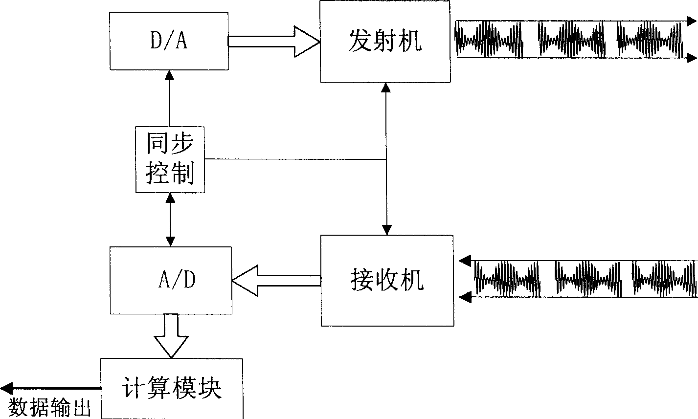
[0099] Such as Figure 6 As shown, the measurement device using the above-mentioned dual-frequency signal time-of-flight measurement method includes a power supply, a signal transmitting module and a signal receiving module, and also includes a digital circuit module integrated by a D / A, A / D converter and a synchronous controller and a calculation module, the computing module is CPU or PDSP. Among them, the signal transmitting module includes a modulator and a transmitter, the signal mode modulated by the modulator is provided by the A / D channel of the digital circuit module, and the modulator controls the transmitter to transmit the signal; the signal receiving module includes a receiver, a reference signal receiver and a modulation Circuit, the receiver converts the received signal into an electrical signal, which is input to the A / D channel of the digital circuit thr...

Embodiment 3

[0106] Such as Figure 5 As shown, a dual-frequency signal time-of-flight measurement method has the following steps:

[0107] In the first step, the transmitter transmits a group of superimposed signals y predetermined in D / A by dual-frequency signals, and the transmission time of the predetermined waves is t p , at the same time the synchronous controller controls the counter to start at the system clock frequency f sys count, and have

[0108] y=sin(2πf 1 t)+sin(2πf 2 t), (2-1)

[0109] t p > 1 abs ( f 1 - f 2 ) + 2 × t per , - - - ( 2 - 2...


PUM


Abstract

The invention discloses a two frequency signal flying time measuring method and the device that emits two frequency signal superposing signal preset in D/A, emitting time span is tp and starting timing, receiving signal of returning after a time span until the signal intensity is 5-10 times over the background noise stopping timing, taking A/D converting, and calculating the accurate flying time. The device includes power supply, signal emitting module, signal receiving module, calculating module, D/A, A/D, and synchronization controller. The invention has the advantages of wide range, high accuracy, and high dynamic response speed.

Description

technical field [0001] The present invention relates to the technical field of a signal ranging method and a device thereof, in particular to a signal time-of-flight measuring method and a measuring device thereof. Background technique [0002] Active radar systems usually transmit signals through the signal transmitter, and the signal receiver receives the reflected signal of the target to analyze the distance, speed and other characteristics of the target. And there is a type of ranging radar, such as: laser ranging radar, ultrasonic ranging radar (also called laser (ultrasonic) ranging machine), which calculates the time difference from transmission to reception of the signal, that is, the flight time of the signal, and then compares it with the speed Multiply to get the distance between the target and the signal transmitter. Among them, the measurement of signal time-of-flight becomes the key. Accurate and high-speed signal time-of-flight measurement can greatly improve...

Claims


Application Information

Patent Timeline
IPC IPC(8): G01S13/32G01S15/32G01S17/36
Inventor 程昕肖毅腓
Owner 成都中科动态仪器有限公司
Why Eureka
Try Eureka