
Cylinder type ultra-high-pressure sensor of side cavity oil charging structure

An ultra-high pressure, cylindrical technology, which is applied in the direction of fluid pressure measurement by changing the ohmic resistance, can solve the problems of small resistivity, sensor stability influence, and poor signal-to-noise ratio

Inactive Publication Date: 2013-07-10
XI AN JIAOTONG UNIV
View PDF9 Cites 4 Cited by
  • Summary
  • Abstract
  • Description
  • Claims
  • Application Information

AI Technical Summary

Problems solved by technology

But there are also the following problems: 1) The maximum range does not exceed 150MPa; 2) The measured medium must not only be compatible with the housing material, but must also be compatible with silicon, glass and packaging materials, so the application range is relatively narrow
However, this type of sensor also has certain shortcomings: 1) If the sensitive element is based on the metal resistance effect, such as a sputtered film or a pressure sensor using a high-temperature foil metal strain gauge, the sensitivity of the sensor is very low due to the small resistivity of the metal. Small (only a few mV / V), so the signal-to-noise ratio is poor, and the requirements for subsequent signal processing circuits are high; 2) If the sensitive component is measured by measuring the displacement generated by the elastic body, the sensitive component needs to be strictly controlled during the packaging process The positional relationship with the elastic body, otherwise the stability of the sensor will be affected. In addition, increasing the wall thickness of the general cylindrical ultra-high pressure sensor will affect the sensitivity of the sensor, making the output of the sensor smaller

Method used


Image

  • Cylinder type ultra-high-pressure sensor of side cavity oil charging structure
  • Cylinder type ultra-high-pressure sensor of side cavity oil charging structure
  • Cylinder type ultra-high-pressure sensor of side cavity oil charging structure

Examples


Embodiment Construction

[0020] The structural principle and working principle of the present invention will be described in more detail below in conjunction with the accompanying drawings.

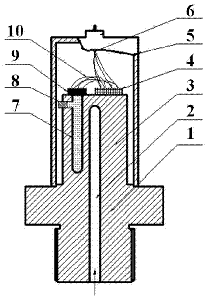
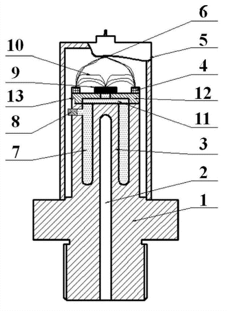
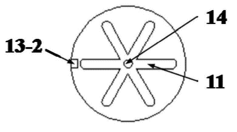
[0021] refer to figure 1 , a cylindrical ultra-high pressure sensor with a side chamber oil-filled structure, including an elastic element base 1, the upper part of the elastic element base 1 is a pressure-bearing cylinder 3, and the center of the pressure-bearing cylinder 3 is a pressure-bearing hole 2, the bearing The side wall of the pressure cylinder 3 is provided with an oil-filled cavity 7 (that is, a single-hole structure), the upper end of the oil-filled cavity 7 communicates with the top of the pressure-bearing cylinder 3, and the sensitive element 9 is assembled on the upper end of the oil-filled cavity 7. The sensitive element 9 is provided with a Wheatstone bridge, and the Wheatstone bridge is connected to the adapter plate 4 by the gold wire lead 10; the adapter plate 4 is installed on the top of the...


PUM

PropertyMeasurementUnit
Sensitivityaaaaaaaaaa

Abstract

A cylinder type ultra-high-pressure sensor of a side cavity oil charging structure comprises an elastic element base, wherein the upper portion of the elastic element base is a pressure bearing cylinder, a pressure bearing hole is formed in the center of the pressure bearing cylinder, and the side wall of the pressure bearing cylinder is provided with one or more than one oil charging cavity. A Wheatstone bridge of a sensitive element is connected with a patch board through a gold wire lead, one end of a cable is connected with the output of the patch board, the other end of the cable is connected with an external circuit, incompressible silicone oil is filled in the oil charging cavity, pressure of measured media directly acts inside the pressure bearing hole, the oil charging cavity produces size deformation which is directly proportional to the measured pressure, and the deformation is transmitted to the sensitive element through the incompressible silicone oil. On the basis of the monocrystalline silicon piezoresistive effect, resistance of four voltage dependent resistors on the sensitive element changes, under drive of a stabilized power source, the four voltage dependent resistors constitute the Wheatstone bridge to output electric signals which are directly proportional to the measured pressure, and therefore detection of ultra-high-pressure can be conducted. The cylinder type ultra-high-pressure sensor can bear pressure more than 1.5 GPa.

Description

technical field [0001] The invention relates to a pressure sensor, in particular to a cylindrical ultra-high pressure sensor with a side cavity oil-filled structure. Background technique [0002] Pressure sensors have always been the focus of research and development because of the huge market demand. Up to now, many products have been based on the working principles of piezoresistive, piezoelectric and strain gauge. The measuring range of these sensors is mainly between 1MPa and 100MPa. , it is more difficult to realize for high-range ultra-high pressure sensor and low-range micro-pressure sensor. There are many application requirements for ultra-high pressure measurement in industrial development and national defense construction. Not only are there many applications in industrial production, but also weapon systems need real-time monitoring of GPa-level pressure. However, due to the blockade of foreign technologies and the late development of related technologies in my c...

Claims


Application Information

Patent Timeline
Patent Type & Authority Applications(China)
IPC IPC(8): G01L9/06
Inventor 赵立波郭鑫蒋庄德乔智霞赵玉龙苑国英
Owner XI AN JIAOTONG UNIV
Learn More