Unlock instant, AI-driven research and patent intelligence for your innovation.

Method for making lattice holographic rainbow optically-variable image

A production method, plain surface technology, applied in the direction of instruments, etc., can solve problems such as difficulty in meeting application requirements and inlaying other images, and achieve the effect of easy acquisition and lower technical requirements

Active Publication Date: 2006-09-27
SUZHOU UNIV +1
View PDF0 Cites 2 Cited by
  • Summary
  • Abstract
  • Description
  • Claims
  • Application Information

AI Technical Summary

Problems solved by technology

[0006] On the other hand, with the continuous deepening of market applications, the aesthetic effect of the original plain grating can no longer meet the application requirements. In terms of use function, it is necessary to have both the aesthetic effect of plain rainbow and anti-counterfeiting function. Various light-changing images with dynamic, stereo and encryption are added to the rainbow grating
It is very difficult to inlay other images, especially dynamic light-variable images, on the above-mentioned holographic interference method for making plain rainbow gratings, so it is difficult to meet the above application requirements

Method used


Image

  • Method for making lattice holographic rainbow optically-variable image
  • Method for making lattice holographic rainbow optically-variable image
  • Method for making lattice holographic rainbow optically-variable image

Examples


Embodiment 1

[0046] Example one: see attached Figure 4 Attached Picture 10 As shown, a method for making a lattice plain rainbow light-variable image includes the following steps:

[0047] (1) Prepare an optical element with orthogonal light spot output, the effective area of ​​which is no less than 5mm×5mm and no more than 15mm×15mm. The orthogonal light spot output refers to the four orthogonal light spot diffraction terms ( 1,0)(-1,0)(0,1)(0,-1);

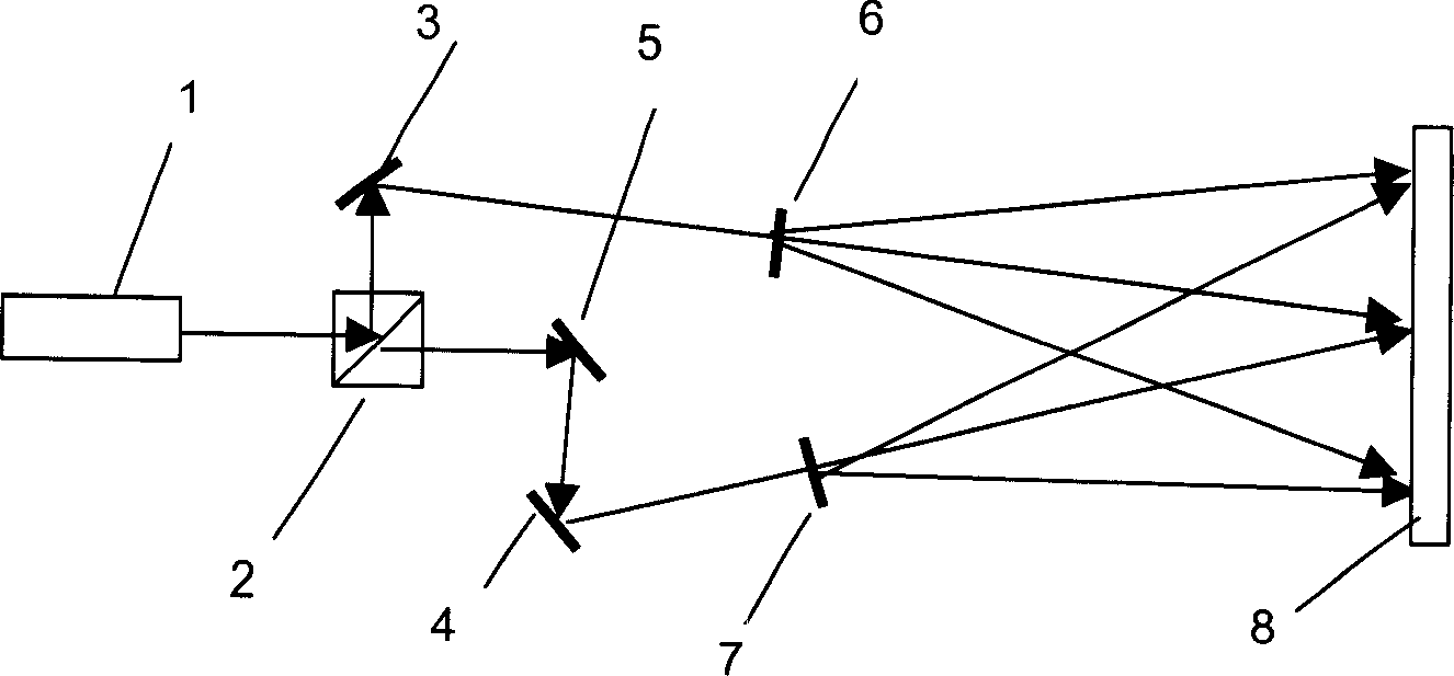
[0048] (2) Construct a 4F optical system, the light emitted by the laser light source is treated as incident light after collimation processing and diaphragm, the recording material is placed on the image plane position of the 4F optical system, and the optical element obtained in step (1) is placed in its transformation On the plane, as a beam splitting element, the incident light is divided into four beams. After the lens is formed into an image, an interference fringe unit is formed on the surface of the recording material. The front focal l...

Embodiment 2

[0060] Embodiment 2: A method for making a rainbow light variable image of a lattice plain surface, including the following steps:

[0061] (1) Prepare an optical element with orthogonal light spot output, the effective area of ​​which is no less than 5mm×5mm and no more than 15mm×15mm. The orthogonal light spot output refers to the four orthogonal light spot diffraction terms ( 1,0)(-1,0)(0,1)(0,-1);

[0062] (2) Construct a 4F optical system, the light emitted by the laser light source is treated as incident light after collimation processing and diaphragm, the recording material is placed on the image plane position of the 4F optical system, and the optical element obtained in step (1) is placed in its transformation On the plane, as a beam splitting element, the incident light is divided into four beams. After the lens is formed into an image, an interference fringe unit is formed on the surface of the recording material. The front focal length of the 4F optical system is grea...


PUM

PropertyMeasurementUnit
Coherence lengthaaaaaaaaaa

Abstract

This invention relates to a method for making lattice holographic rainbow optically-variable image, which comprises the following steps: (1) preparing an optical element with orthogonal light spot output; (2) building a 4F optical system with a laser of short coherent length, putting the former element on the transformation plane to split the incident beam into four beams as a beam-splitting element; forming the interface band unit on record material surface by lens imaging; (3) changing the relative position of the optical system and record material to record the interface band unit and point-by-point photo etch the prime grating. This invention reduces the manufacture technique request greatly, can obtain different diffraction effects, and inlays with the digital optical-variable image mutually.

Description

Technical field [0001] The invention relates to a process and equipment for obtaining a holographic image, in particular to a method for making a dot-matrix plain rainbow (large-format orthogonal rainbow) light-variable image. Background technique [0002] In the application of laser holography, because the orthogonal grating can observe the characteristics of the rainbow effect at any angle, the large-format orthogonal rainbow effect (primary rainbow grating) material has become the most widely used and most important laser material at present. Large-scale applications have been obtained in the fields of printing, packaging, mobile phones and household appliances. [0003] The traditional method of making a plain rainbow light-changing image, see attached figure 1 The laser beam generated by the laser light source 1 is split into two beams by the beam splitter 7, and the beams are expanded by the reflectors 17, 18, 19 and the beam expanders 20, 21, formin...

Claims


Application Information

Patent Timeline
IPC IPC(8): G03H1/04
Inventor 陈林森周小红魏国军解正东汪振华解剑锋邵洁
Owner SUZHOU UNIV