Grid control signal generation apparatus and method for liquid crystal display

A liquid crystal display, gate control technology, applied to static indicators, instruments, etc., to achieve the effect of reducing the number of wires

Inactive Publication Date: 2006-10-04
HIMAX TECH LTD
View PDF0 Cites 7 Cited by
  • Summary
  • Abstract
  • Description
  • Claims
  • Application Information

AI Technical Summary

Problems solved by technology

[0005] However, conventional LCDs using Chip On Glass (COG) require more flexible circuit boards. For example, in figure 1 For example, 11 pieces are required, and the production process still needs to be simplified

Method used


Image

  • Grid control signal generation apparatus and method for liquid crystal display
  • Grid control signal generation apparatus and method for liquid crystal display
  • Grid control signal generation apparatus and method for liquid crystal display

Examples


Embodiment Construction

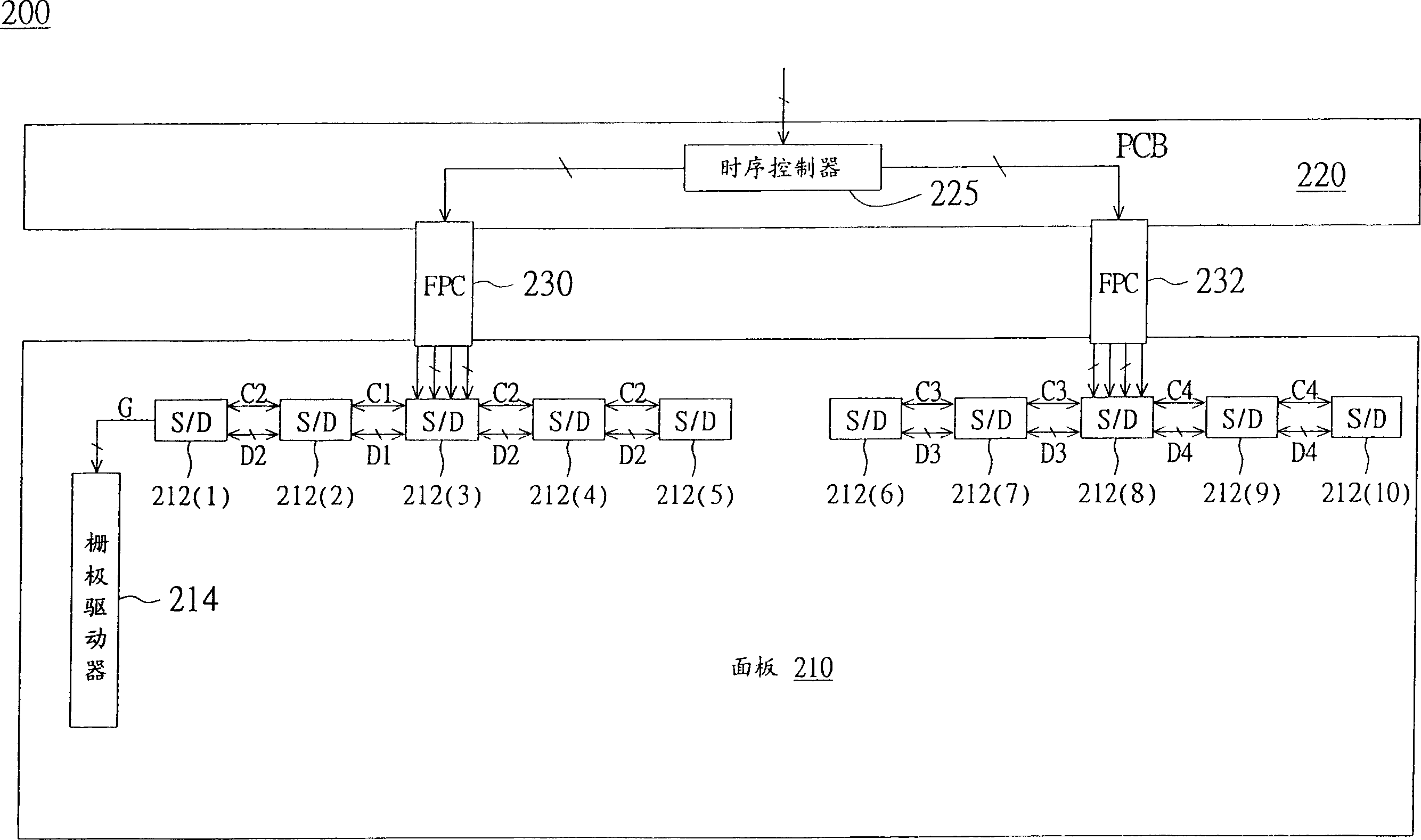
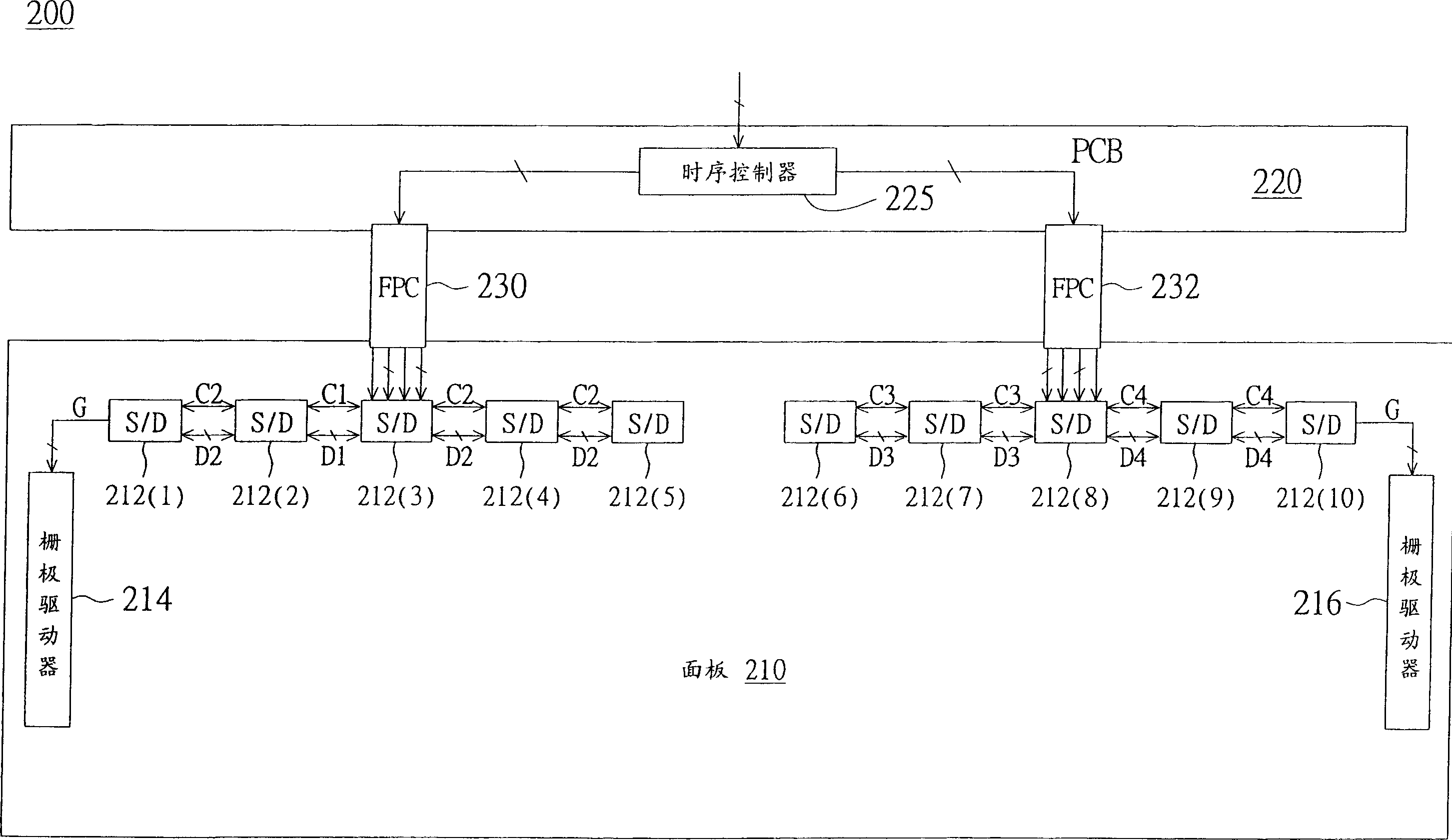
[0050] Please refer to Figure 2A , which shows a schematic diagram of a liquid crystal display using Chip On Glass (COG) package according to a preferred embodiment of the present invention. The liquid crystal display 200 includes: a panel 210, a plurality of source drivers (Source Driver, S / D) 212(1)-211(10), at least one gate driver (Gate Driver) 214, a printed circuit board 220 and a flexible circuit board 230 and 232. The source driver 212 and the gate driver 214 are disposed on the glass substrate of the panel 210 . The timing controller 225 is arranged on the printed circuit board 220 to receive image data and control signals, and then transmit them to the source drivers 212(3) and 212(8) through flexible circuit boards (FPC) 230 and 232 after processing. The source drivers 212(3) and 212(8) respectively transmit the received image data and source control signals to the adjacent source drivers 212(1), 212(2), 212(4) through the wires on the glass substrate. ), 212(5)...


PUM


Abstract

The LCD comprises a panel with matrix-arrangement pixel, a time schedule controller to output video data and control signal for source, and grid driver to drive the pixels on panel together with serial multiple source drivers selected according to at least one source/grid control signal.

Description

technical field [0001] The invention relates to a liquid crystal display, in particular to a liquid crystal display adopting chip-on-glass package (Chip On Glass, COG). Background technique [0002] In view of advantages such as lightness, thinness and low radiation, liquid crystal displays have gradually replaced cathode ray tube (CRT) displays and become the mainstream of computer screens and televisions. In addition to improving the display quality of LCDs, such as color, contrast, and brightness, manufacturers are also committed to improving their production technology to speed up the production process and reduce production costs. [0003] The liquid crystal display uses a timing controller, a source driver and a gate driver to drive the liquid crystal panel. The traditional timing controller, source driver and gate driver are soldered to a printed circuit board (Printed Circuit Board, PCB), and then electrically connected to the liquid crystal panel through a flexible...

Claims


Application Information

Patent Timeline
Patent Type & Authority Applications(China)
IPC IPC(8): G09G3/36G02F1/133
CPCG09G2370/08G09G2310/0281G09G3/3666G09G2310/04G09G3/3688G09G2330/021G09G3/3611G09G2300/04G09G3/3677
Inventor 陈建儒陈俊荣
Owner HIMAX TECH LTD
Why Eureka
Try Eureka