Method and sensor arrangement for measurement on rolling element bearing

A rolling element and sensor technology, applied in the field of rolling element bearings, can solve problems such as determining the bearing load

Inactive Publication Date: 2006-10-04
AB SKF
View PDF1 Cites 14 Cited by
  • Summary
  • Abstract
  • Description
  • Claims
  • Application Information

AI Technical Summary

Problems solved by technology

Also, due to the non-linear nature of bearings, direct vibration measurements using the b...

Method used


Image

  • Method and sensor arrangement for measurement on rolling element bearing
  • Method and sensor arrangement for measurement on rolling element bearing
  • Method and sensor arrangement for measurement on rolling element bearing

Examples


Embodiment Construction

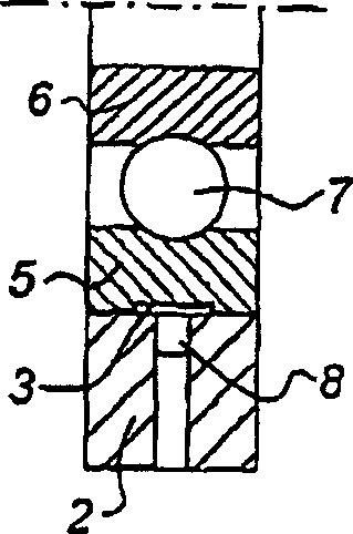
[0035] figure 1 A cross-sectional view of a rolling element bearing 1 , such as a ball bearing or roller bearing, is shown in . The rolling element shaft 1 includes an outer ring 5, an inner ring 6 and several rolling elements 7 (the number of rolling elements 7 in the figure is eight). The outer ring 5 of the rolling element bearing 1 is fixed on the sensor supporter 2, and the supporter 2 forms a fixed world for the rolling element bearing 1. Eight sensors 8 are arranged in the sensor holder 2 opposite the bearing outer ring 5 at a (angular) spacing corresponding to the angular spacing of the rolling elements of the bearing 1 . The sensor 8 can be a displacement sensor or a vibration sensor well known in the art.

[0036] Such as figure 2 As shown in the sectional view of the bearing outer ring 5, there is a recess 3 on its outer peripheral edge. The outer surface of the bearing outer ring 5 is in close contact with the sensor holder 2 . The sensor 8 can thus monitor t...


PUM


Abstract

Method and sensor arrangement for determining a contact force vector acting on a rolling element bearing (1) in operation. Sensor signals are received from a plurality of sensors (8) measuring performance characteristics of the rolling element bearing (1). The received sensor signals are processed to determine the contact force vector. The plurality of sensors (8) are arranged to measure a bearing component deformation, and the step of processing comprises the step of determining the contact force vector using an inverse transformation of a finite element analysis model which describes the rolling element bearing (1). The finite element analysis model is simplified using at least one generalised mode shape, the at least one generalised mode shape being a mathematical description of a natural mode deformation of a component of the rolling element bearing (1), such as the inner or outer ring (5, 6).

Description

technical field [0001] The invention relates to load measurement on rolling element bearings, such as ball and roller bearings. More specifically, the present invention relates to a method and sensor for determining contact force vectors acting on a rolling element bearing during operation, wherein the rolling element bearing comprises an inner ring, an outer ring and rolling elements between several inner and outer rings, The method includes the steps of receiving sensor signals from a plurality of sensors measuring an operational characteristic of the rolling element bearing and processing the received sensor signals to determine a contact force vector. Background technique [0002] Such a load measurement method is known, for example, from US-A-5,140,849, which describes a rolling element bearing with a sensor unit. The sensor unit consists of two sensor elements in the form of strain gauges which effectively measure some operating characteristic of the bearing, such as ...

Claims


Application Information

Patent Timeline
IPC IPC(8): G01L5/00G01M13/04
CPCG01L5/0019G01M13/045F16C19/522F16C19/06G01B11/30G01M13/04
Inventor 汉德瑞克·A.·莫莉盖瑞特·C.·万尼简
Owner AB SKF
Why Eureka
Try Eureka