

Dual-gas source ignition device with oxygen depletion safety device
An oxygen-deficient protection and ignition device technology, which is used in combustion ignition, intermittent spark ignition, gas fuel burners, etc., to achieve the effects of wide application, simple structure, and convenience for production enterprises
- Summary
- Abstract
- Description
- Claims
- Application Information
AI Technical Summary
Problems solved by technology
Method used
Image

Examples
Embodiment 1
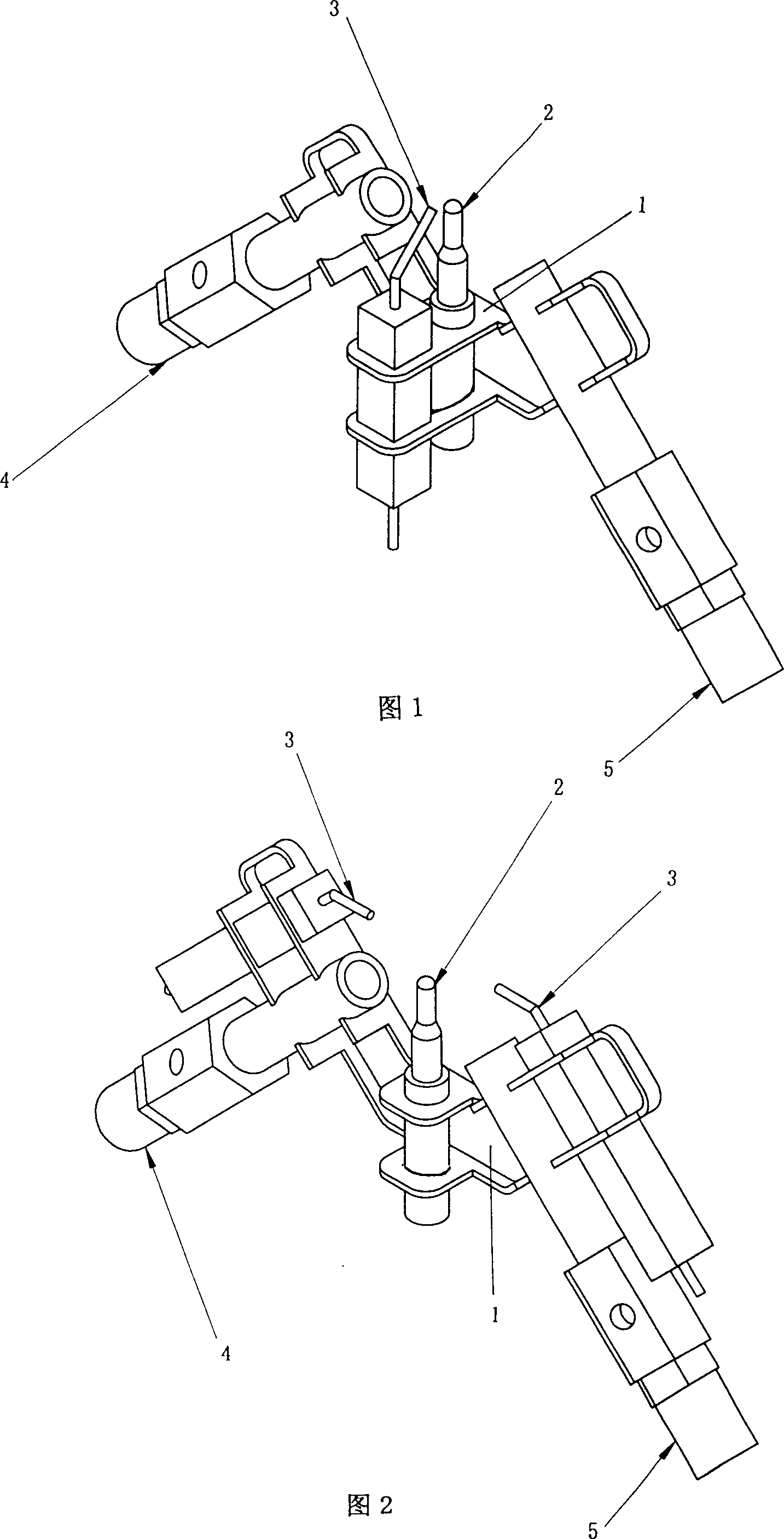
[0021] As shown in Figure 1.
[0022] A double gas source hypoxia protective ignition device for a gas heater, comprising a mounting frame 1, on which a thermocouple 2, a discharge electrode 3, a high calorific value gas ignition nozzle 4, and a low calorific value gas ignition nozzle 5 are installed , the high calorific value gas ignition nozzle 4 and the low calorific value gas ignition nozzle 5 are installed obliquely on the installation frame 1, and the thermocouple 2 is installed between the two, and its top is located at the high calorific value gas ignition nozzle 4 and the low calorific value gas ignition nozzle Near the intersection of the axes of 5, the discharge electrode 3 is installed on the installation frame 1 together with the thermocouple 2, and its discharge end should be located above the thermocouple 2.
[0023] During specific implementation, the discharge electrode 3 can be installed on the mounting frame 1 in addition to being installed on the mounting f...
Embodiment 2
[0025] as shown in picture 2.
[0026] A double gas source anoxic protective ignition device for a gas heater, comprising a mounting frame 1 on which a thermocouple 2, a discharge electrode 3, a high calorific value gas ignition nozzle 4, a low calorific value gas ignition nozzle 5, and a high calorific value gas ignition nozzle 5 are installed. The gas ignition nozzle 4 and the low calorific value gas ignition nozzle 5 are installed obliquely on the mounting frame 1, and the thermocouple 2 is installed between them, and its top is located on the axis of the high calorific value gas ignition nozzle 4 and the low calorific value gas ignition nozzle 5 Near the intersection point, the number of discharge electrodes 3 is two, the discharge end of one discharge electrode 3 is located above the high calorific value gas ignition nozzle 4, and the discharge end of the other discharge electrode 3 is located above the low calorific value gas ignition nozzle 5. They are all fixedly insta...
Embodiment 3
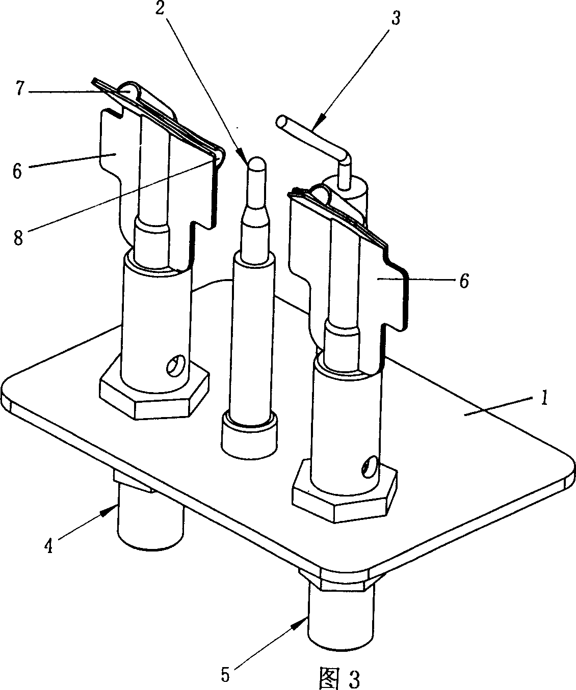
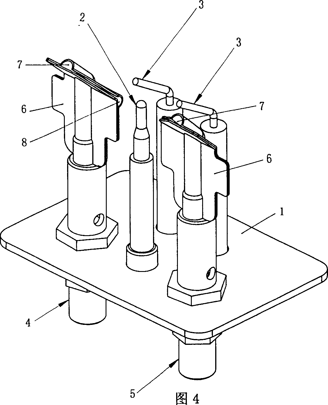
[0028] As shown in Figure 3.
[0029] A double gas source hypoxia protective ignition device for a gas heater, comprising a mounting frame 1 on which a thermocouple 2, a discharge electrode 3, a high calorific value gas ignition nozzle 4, and a low calorific value gas ignition nozzle 5 are installed. High value gas ignition nozzle 4 and low calorific value gas ignition nozzle 5 are installed in parallel on the mounting frame 1, and the outlets of high calorific value gas ignition nozzle 4 and low calorific value gas ignition nozzle 5 are equipped with deflectors 6, deflectors 6 is respectively provided with an ignition injection hole 7 and a gas injection hole 8 for hypoxia protection. The thermocouple 2 is installed between the two injection holes 8, and its top is not lower than the horizontal position of the two injection holes 8. The discharge terminal should be located above the thermocouple 2.
[0030] The discharge electrode 3 can be installed directly on the mounting ...
PUM
 Abstract
Description
Claims
Application Information