Refrigeration device

A refrigeration device and refrigerant technology, which is used in household refrigeration devices, refrigerators, refrigeration components, etc., to achieve the effects of improving the refrigeration coefficient, improving performance, and reducing compression power

Inactive Publication Date: 2006-10-18
THERMAL ANALYSIS PARTNERS +1
View PDF1 Cites 27 Cited by
  • Summary
  • Abstract
  • Description
  • Claims
  • Application Information

AI Technical Summary

Problems solved by technology

Therefore, the refrigeration effect can be increased, and the performance can be effectively improved compared with the existing device, but the cooling effect produced by the first refrigerant flow that is cooled before the second refrigerant flow is decompressed depends on the first Refrigerant flow and 2nd refrigerant flow flow through the intermediate heat exchanger, so in order to achieve the best performance improvement, this refrigerant flow must be properly controlled

Method used


Image

  • Refrigeration device
  • Refrigeration device
  • Refrigeration device

Examples


Embodiment 2

[0172] In addition, in the separate cycle of the above-mentioned embodiment, the main expansion valve 106 (main throttling device) and the auxiliary expansion valve 109 (auxiliary throttling device) are formed separately to control throttling separately, but it goes without saying that the main expansion valve 106 (main throttling device) can also be divided into two parts. Flow device and auxiliary throttling device are integrated. At this time, the high-pressure refrigerant output from the radiator 105 is not divided into a main refrigerant flow and an auxiliary refrigerant flow before the intermediate heat exchanger 107 as in the above embodiment, and all the refrigerant flows through the intermediate heat exchanger 107 For cooling, it is necessary to diverge them after passing through the intermediate heat exchanger 107 . Figure 11 It is a schematic diagram of an expansion device of an embodiment in which the above-mentioned two expansion devices are integrated.

[0173]...

Embodiment 3

[0177] Moreover, the refrigerating device of the present invention is not limited to the device of the above-mentioned embodiment, and can also be applied to a refrigerating device in which a circuit is formed by other multiple evaporators and heat radiators. Figure 12 is a block diagram of the refrigeration device of this embodiment. Figure 12 The refrigeration unit 300 is shown as a split-cycle unit capable of mixed operation for cooling, heating and / or hot water supply. The split cycle of this embodiment consists of the low-pressure side compressor 301 and the high-pressure side compressor 302 of this occasion as the compression device; the first heat exchanger 305, the second heat exchanger 306 and the third heat exchanger as the utilization side heat exchanger. The exchanger 307; the fourth heat exchanger 308 which is a heat source side heat exchanger, etc. are comprised.

[0178] The first heat exchanger 305 and the second heat exchanger 306 are heat exchangers used f...

Embodiment 4

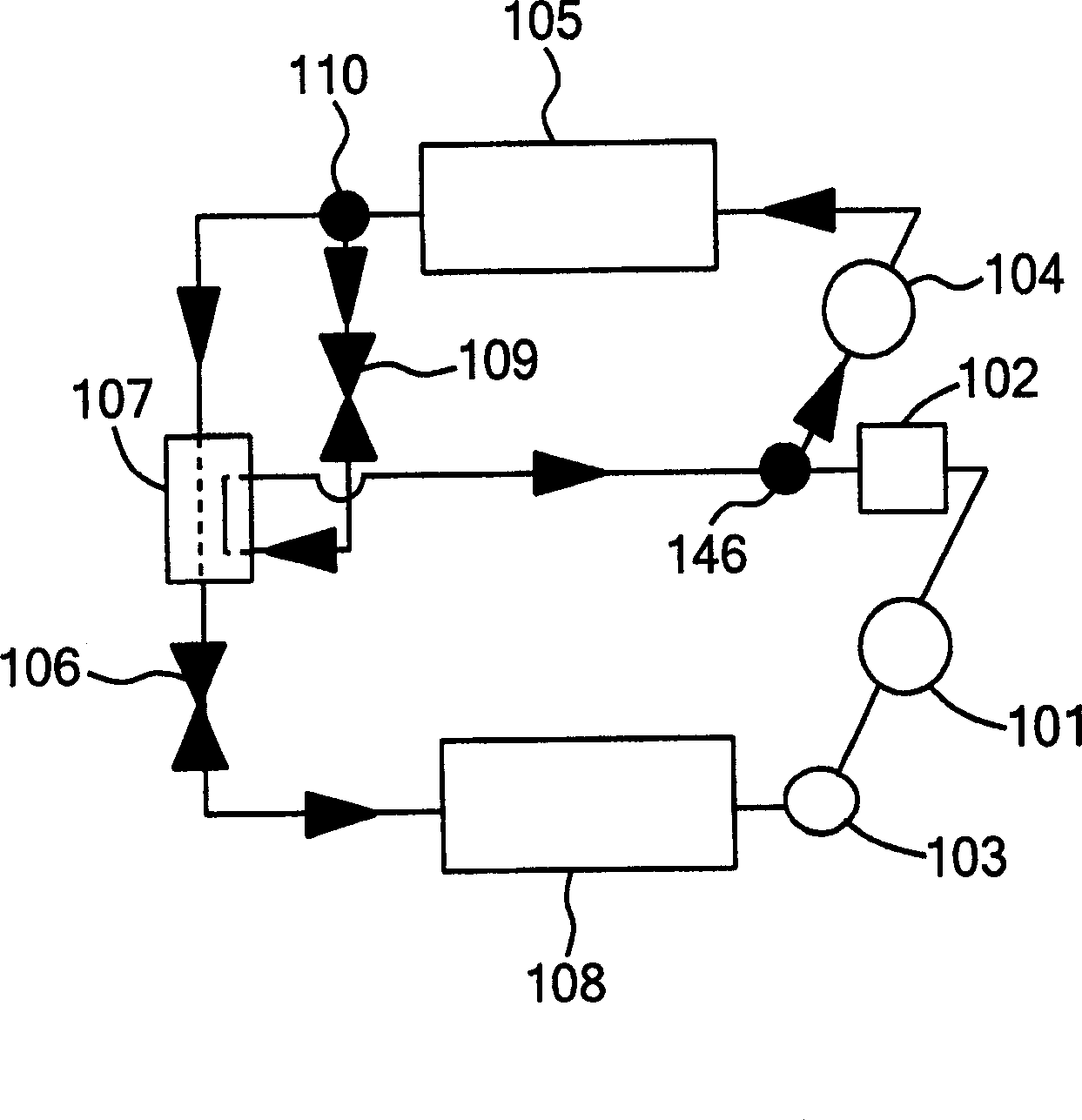
[0195] Figure 13 is a block diagram of a split cycle device according to another embodiment of the present invention. Two evaporators 405 and 406 capable of cooling in different temperature ranges are provided in the split circulation device 400 of this embodiment. That is, the split cycle device 400 of this embodiment consists of a low-pressure side compression device 401 constituting a compression device, an intercooler 412, a confluence device 413 as a converging device for converging two refrigerant flows, and a high-pressure side compression device that also constitutes a compression device. 402, heat radiator 403, flow splitter 404 as flow splitting device, intermediate heat exchanger 410, internal heat exchanger 415, auxiliary expansion valve 409 as auxiliary throttling device, main expansion valve 407 as main throttling device, the same The main expansion valve 408, the evaporators 405 and 406 as the main throttling means are constituted. The throttling amount of th...


PUM


Abstract

The refrigerating device of the invention is used to improve the refrigerating capacity of the evaporator in the refrigerating device and improve the performance. The refrigerant flowing out of the heat radiator (105) is divided into two streams, and the first refrigerant stream flows into the first flow path of the intermediate heat exchanger (107) through the auxiliary expansion valve (109), and the second refrigerant stream After flowing through the second flow path of the intermediate heat exchanger, it flows into the evaporator (108) through the main expansion valve (106) as the main throttling device, and in the intermediate heat exchanger, the first refrigerant flow and the second refrigerant flow The refrigerant flow performs heat exchange, the refrigerant flowing out of the evaporator is sucked into the compression element on the low stage side (low pressure part of the compression device), and the above-mentioned first refrigerant flow flowing out from the intermediate heat exchanger is sucked into the compression element on the high stage side ( the middle pressure part of the compression device). The pressure of the intermediate pressure portion of the compression device is determined by controlling the auxiliary expansion valve as the auxiliary throttling device based on the suction pressure and discharge pressure of the compression device.

Description

technical field [0001] The present invention relates to a refrigerating device used in freezing, refrigerating, air-conditioning, heat pump, etc., and particularly relates to a refrigerating device comprising a first refrigerant flow (auxiliary flow) and a second refrigerant flow (main flow) adjusted by prescribed control characteristics refrigeration unit. Background technique [0002] This kind of refrigerating device has always constituted a refrigeration cycle by a compression device, a heat radiator, and a throttling device. Evaporate, and the refrigerant that evaporates at this time cools the surrounding air. In recent years, Freon-based refrigerants cannot be used in such refrigeration devices due to natural environmental problems and the like. Therefore, it is known (for example, refer to Patent Document 1) to try to use carbon dioxide, which is a natural refrigerant, as a substitute for Freon-based refrigerants. This carbon dioxide refrigerant is a refrigerant wi...

Claims


Application Information

Patent Timeline
Patent Type & Authority Applications(China)
IPC IPC(8): F25B7/00
CPCF25B1/04F25B1/10F25B5/02F25B9/008F25B40/00F25B2309/061F25B2400/13F25B2600/17F25B2600/2509F25B2700/1931F25B2700/1933F25D11/022F25B2400/072F25B41/325
Inventor R·雷德马彻石原寿和H·赫夫Y·黄大竹雅久向山洋桑原修上村一朗
Owner THERMAL ANALYSIS PARTNERS
Why Eureka
Try Eureka