CCD splicing system

A splicing system and splicing device technology, applied in the field of CCD splicing systems, can solve the problems of inability to splice back-illuminated CCDs, working distance limitations, etc., and achieve the effect of large-field-of-view format imaging and push-broom imaging

Inactive Publication Date: 2006-10-18
西安中科光机投资控股有限公司
View PDF0 Cites 11 Cited by
  • Summary
  • Abstract
  • Description
  • Claims
  • Application Information

AI Technical Summary

Problems solved by technology

[0006] The invention solves the technical problem that the back-illuminated CCD cannot be spliced ​​due to the limitation of the working distance in the background technology of using a universal tool microscope for CCD splicing

Method used


Image

  • CCD splicing system

Examples


Embodiment Construction

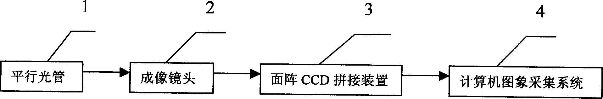
[0014] see figure 1 , the present invention comprises collimator 1, imaging lens 2, CCD splicing device 3 and computer image acquisition system 4, and collimator 1 is arranged in front of imaging lens 2, and imaging lens 2 is arranged in front of CCD splicing device 3, computer image The acquisition system 4 is connected with the CCD splicing device 3 . The CCD splicing device 3 is an area array CCD splicing device or a line array CCD splicing device.

[0015] Collimator 1 is a standard light pipe with proper focal length.

[0016] The imaging lens 2 is a lens matching the pixel size of the spliced ​​CCD.

[0017] The computer image acquisition system 4 is an image acquisition system for the spliced ​​CCD type. That is, when the linear array CCD is spliced, it is a linear array CCD splicing image acquisition system, and when the area array CCD is spliced, it is an area array CCD splicing image acquisition system.

[0018] Taking the splicing area array CCD as an example, w...


PUM


Abstract

The CCD splicing system includes a collimator, an imaging lens, a CCD splicing device and a computerized image acquiring system arranged successively. The present invention is superior to available CCD splicing system with universal tool microscope, which has limited work distance and can not splice back lighted CCD device.

Description

1. Technical field [0001] The invention relates to a CCD splicing system. 2. Background technology [0002] In the development process of aerospace optical remote sensors, due to the limitation of the size of the photosensitive area of ​​the CCD detector, it is sometimes difficult for a CCD to meet the requirements of the optical remote sensor for the ground imaging width. In order to obtain the imaging index of a larger field of view, the CCD splicing is needed to increase the width, and CCD splicing technology came into being. The existing CCD splicing methods can be divided into linear array CCD splicing and area array CCD splicing. Most of the current splicing methods solve the problem of linear array CCD splicing, because they only need to meet the linear array CCD common image plane and linearity requirements. The splicing of linear array CCD can only meet the working mode of linear array push-broom, while the splicing of area array CCD needs to meet the consistency r...

Claims


Application Information

Patent Timeline
Patent Type & Authority Applications(China)
IPC IPC(8): G01S7/48G01S7/481G01S17/89
Inventor 阮萍杨建峰邱跃洪许嘉源乔卫东
Owner 西安中科光机投资控股有限公司
Why Eureka
Try Eureka