Supercharge Your Innovation With Domain-Expert AI Agents!

Light valve

A light valve and light processing technology, applied in optics, light sources, optical components, etc., can solve the problems of reduced contrast of projected images, difficult to operate, large lighting equipment, etc., to achieve the effect of compact lighting equipment

Inactive Publication Date: 2006-10-18
BARCO NV
View PDF0 Cites 0 Cited by
  • Summary
  • Abstract
  • Description
  • Claims
  • Application Information

AI Technical Summary

Problems solved by technology

[0006] A disadvantage of the known rectangular light valve is that when only a circular area of ​​the array of light processing elements is illuminated, it can be observed that the image constructed on the screen is surrounded by a slightly illuminated ring, which Reduces the contrast of the projected image
[0008] However, such an additional lens obviously increases the cost of the associated light emitting device
[0009] Furthermore, the additional lens results in a larger and heavier luminaire and thus more difficult to handle

Method used


Image

  • Light valve
  • Light valve
  • Light valve

Examples


Embodiment Construction

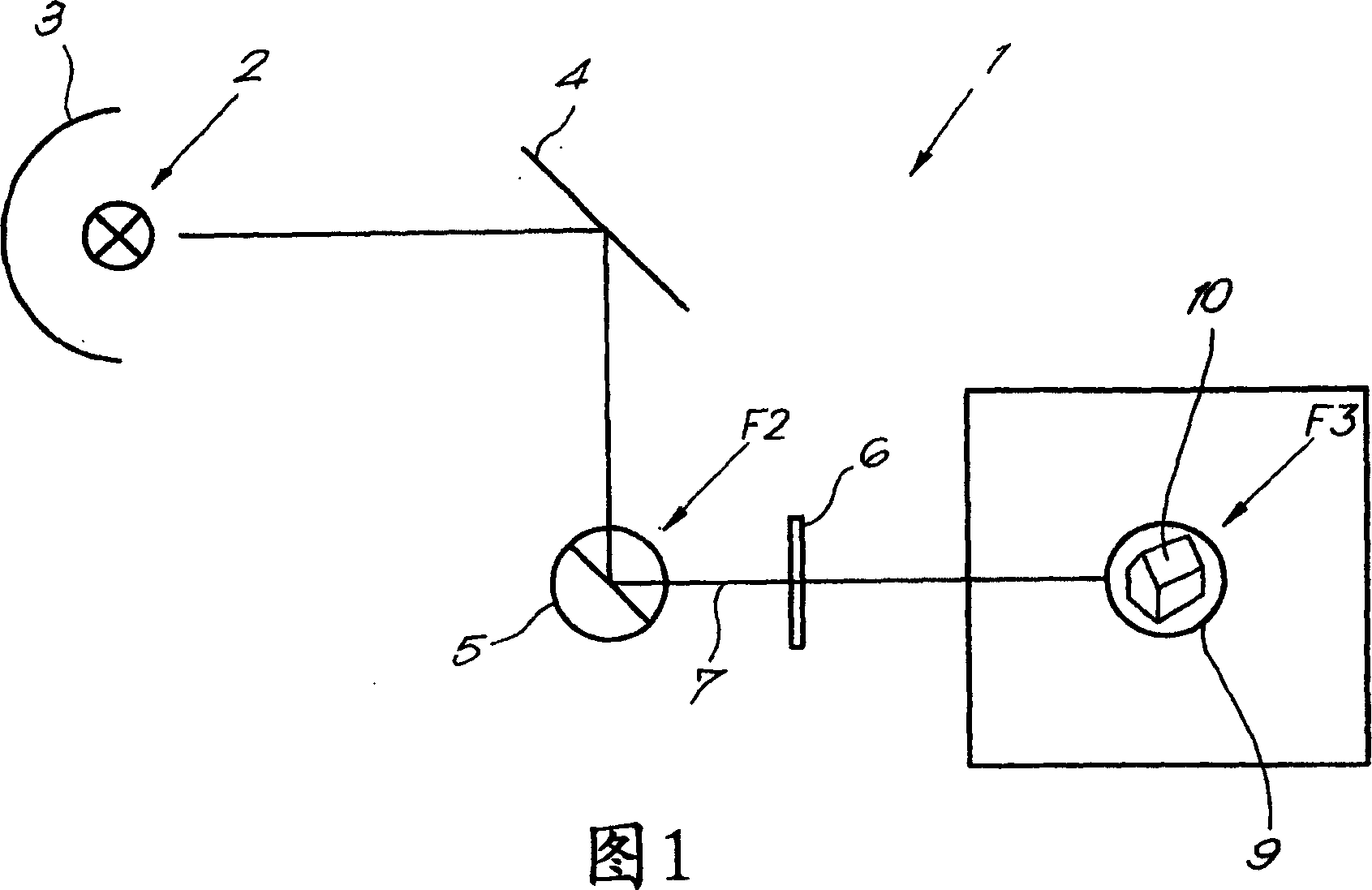
[0018] As shown in FIG. 1 , a lighting device 1 generally consists of a light source 2 , preferably provided with one or more reflectors 3 , a reflector 4 , a light valve 5 and a lens 6 .

[0019] The light source 2 may be of any kind, but is preferably a light source 2 that can generate stable light emission, such as a low pressure metal halide lamp.

[0020] The reflector 3 and mirror 4 are intended to parallelize the light emitted by the light source 2 in order to generate the parallel light beam 7 directed to the light valve 5 .

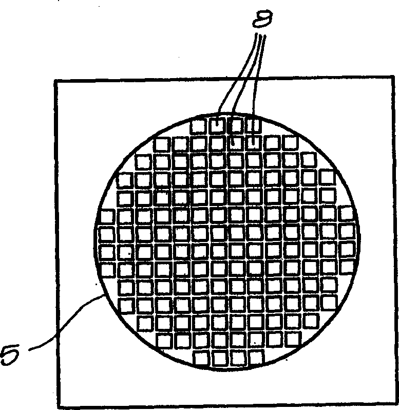
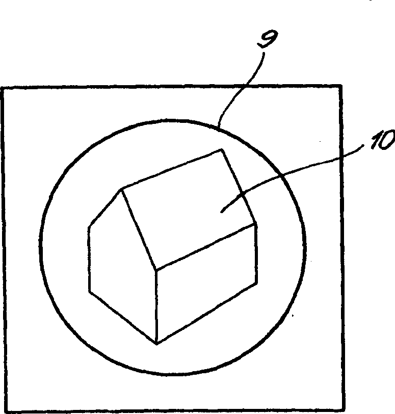
[0021] According to the invention, the light valve 5 consists of an array of light processing elements 8 arranged on a non-rectangular outline, more particularly on an outline substantially corresponding to the outline 9 of the image 10 to be constructed.

[0022] Therefore, if figure 2 and image 3 As shown, where the image 10 to be constructed has a substantially circular outline, the present invention proposes the use of, for example, a circ...


PUM


Abstract

A light valve meant to be used in a lighting device, comprising an array of light processing elements that are arranged in an outline substantially corresponding to the overall contour of an image to be built.

Description

technical field [0001] The present invention relates to a light valve, in particular a reflective light valve or a transmissive light valve designed for use in lighting devices such as so-called gobos. Background technique [0002] It is known to use light valves in lighting devices such as lens shades, which are lighting devices designed for light displays on a stage to project images and move them across said stage . [0003] Such a lens shade typically consists of a light source that produces a light beam, a light valve for processing the light beam to construct an image, and a lens through which the processed light beam is projected onto a screen, wall, etc. [0004] Known light valves used in the above-mentioned lighting devices consist of a rectangular array of light processing elements such as mirrors or liquid crystals. [0005] Thereby each of said elements corresponds to a pixel of the projected image and can be individually directed at the location where the rel...

Claims


Application Information

Patent Timeline
Patent Type & Authority Applications(China)
IPC IPC(8): G02B5/00F21Y101/00
CPCF21V14/003H04N9/3108H04N9/3152
Inventor 比德·格莱兹尼克·库里尔马茨·卡尔森
Owner BARCO NV
Features
  • R&D
  • Intellectual Property
  • Life Sciences
  • Materials
  • Tech Scout
  • Unparalleled Data Quality
  • Higher Quality Content
  • 60% Fewer Hallucinations
Learn More