Three-switch type power converter

A power converter, three-switch technology, applied in electrical components, control systems, electromechanical devices, etc., can solve the problems of unfavorable switched reluctance motor performance, small winding mutual inductance, etc., to improve commutation performance, increase output power, reduce Effects of small radial forces

Inactive Publication Date: 2006-10-18
NANJING UNIV OF AERONAUTICS & ASTRONAUTICS
View PDF0 Cites 12 Cited by
  • Summary
  • Abstract
  • Description
  • Claims
  • Application Information

AI Technical Summary

Problems solved by technology

However, the winding mutual inductance of the switched reluctance motor is very small, and the energy cannot be transferred to the next working phase by using the winding mutual inductance coupling. The phase current of the sw

Method used


Image

  • Three-switch type power converter
  • Three-switch type power converter
  • Three-switch type power converter

Examples


Embodiment Construction

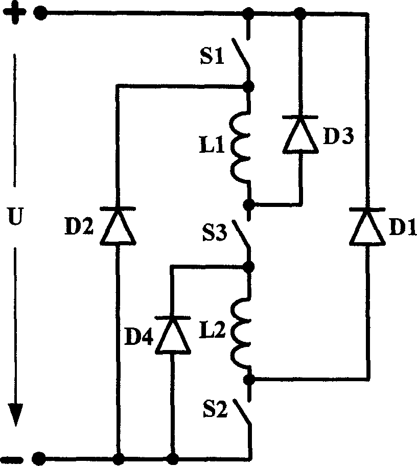
[0012] Such as figure 1 As shown, each phase circuit of the three-switch power converter of the switched reluctance motor includes two switching elements and two diodes, and the switching element S 1 with motor coil L 1 in series, the switching element S 2 with motor coil L 2 In series, the cathode of the diode D1 is connected to the positive pole of the power supply, and the switching element S 2 with motor coil L 2 Between; the anode of the diode D2 is connected to the negative pole of the power supply, and the cathode is connected to the switching element S 3 with motor coil L 1 between the two series connected motor coils L 1 and L 2 A controllable switching device S is connected in series between 3 , and at the controllable switching device S 3 Add a diode D between both ends and the positive and negative poles of the power supply 3 、D 4 As an auxiliary diode, where the diode D 3 The cathode is connected to the positive pole of the power supply, and the anode ...


PUM


Abstract

A power converter of three switches type is prepared as series-connecting a controllable switching element between coils of two series connected motors, adding a diode separately between two end of said switching element and positive as well as negative electrodes of power supply and using it as auxiliary diode, connecting cathode of a diode to positive electrode of power supply and anode of it between motor coil and controllable switching element, connecting anode of another diode to negative electrode of power supply and cathode of it between motor coil and controllable switching element.

Description

1. Technical field [0001] The invention relates to a power converter, in particular to a power converter suitable for switched reluctance motors. 2. Background technology [0002] The structure of the switched reluctance motor is simple, the rotor has no windings, no permanent magnets, the stator has only concentrated windings, and the supporting switching circuit is not complicated. It has high efficiency, convenient control, excellent speed regulation performance, good reliability, and can be used in harsh environments. It is one of the hotspots in motor research at present. [0003] In actual use, the current of each phase of the switched reluctance motor maintains a certain phase sequence and a certain on-off time according to the closed-loop control of the position. When the phase is commutated, the motor quickly feeds back energy to the power supply, and the phase winding current rapidly decays to zero, otherwise negative torque will be produced. Since the motor roto...

Claims


Application Information

Patent Timeline
IPC IPC(8): H02P25/18H02K11/20H02P25/086H02P25/092
Inventor 刘闯周强朱学忠
Owner NANJING UNIV OF AERONAUTICS & ASTRONAUTICS
Why Eureka
Try Eureka