

Pipeline and floor joint position water proof construction method
A technology combining parts and construction methods, applied to building components, building insulation materials, etc., can solve the problems of low integrity rate of waterproof finished products and non-standard appearance, etc., and achieve the effect of reliable waterproof quality, simple construction method and simple construction
- Summary
- Abstract
- Description
- Claims
- Application Information
AI Technical Summary
Problems solved by technology
Method used
Image

Examples
Embodiment 1
[0048] Embodiment 1, the waterproof construction method of the joint between the pipeline and the floor slab
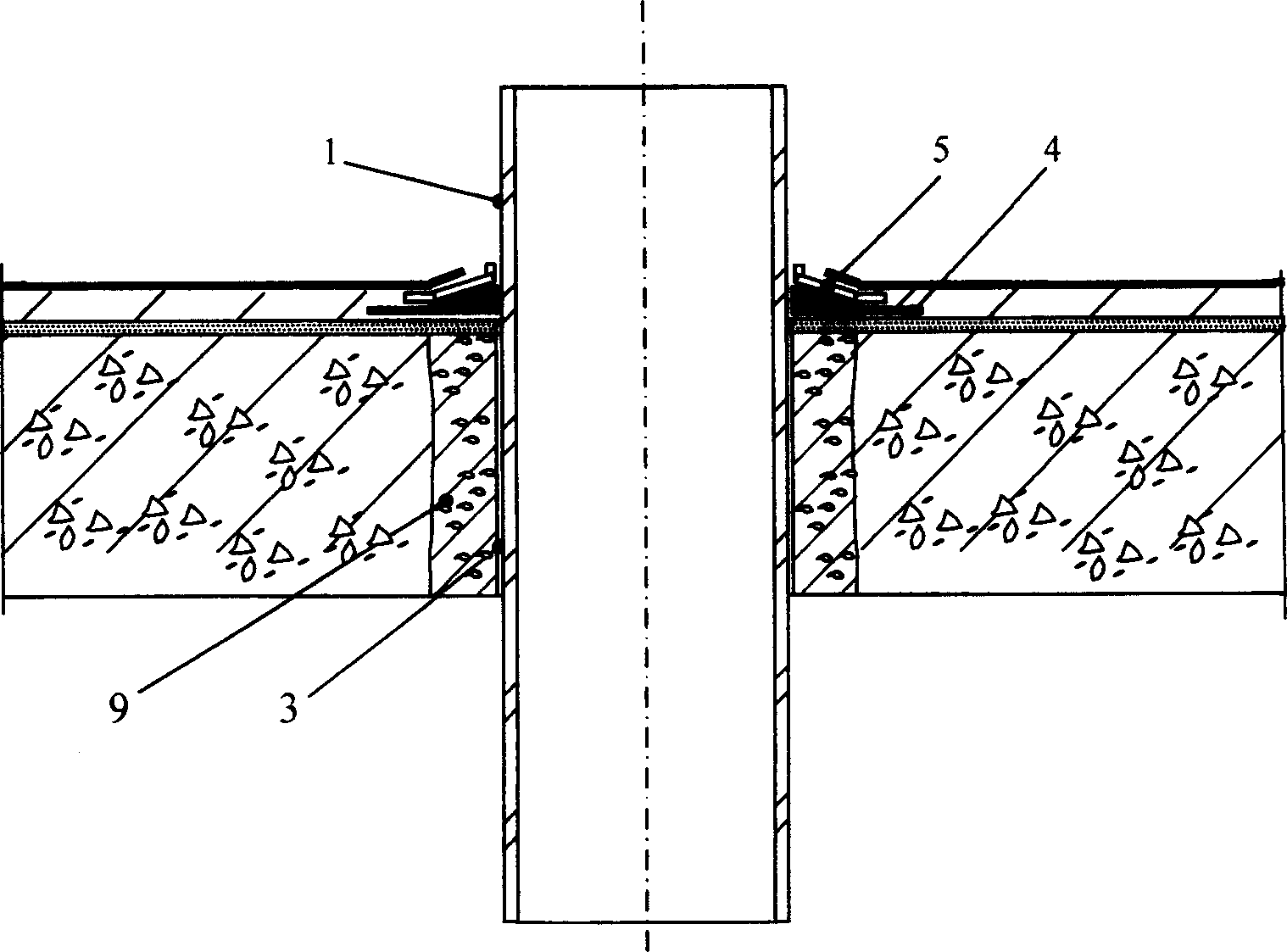
[0049] like figure 1 , the shaping pressure plate 5 is put on the pipeline earlier. Between the outer surface 1 of the pipeline and the hole 2 of the floor slab, fill the gap with concrete 9 for secondary filling, so as to prevent the sealing and waterproofing material from flowing downward when the sealing and waterproofing material is applied thereon. After the concrete 9 is filled, an adhesive hot-melt modified asphalt sealing waterproof material 4 with a temperature of 80-150°C is applied to the joint 3 between the outer surface of the pipe 1 and the floor slab, and the hot-melt modified asphalt The thickness of the thinnest part of the stack is not less than 10-20 mm. The hot-melt modified asphalt is applied on the outer surface 1 of the pipe, and then on the floor joint 3 and the surrounding floor surface, and the hot-melt modified asphalt forms an annular bel...
Embodiment 2
[0050] Embodiment 2, the waterproof construction method of the joint between the floor drain and the floor slab
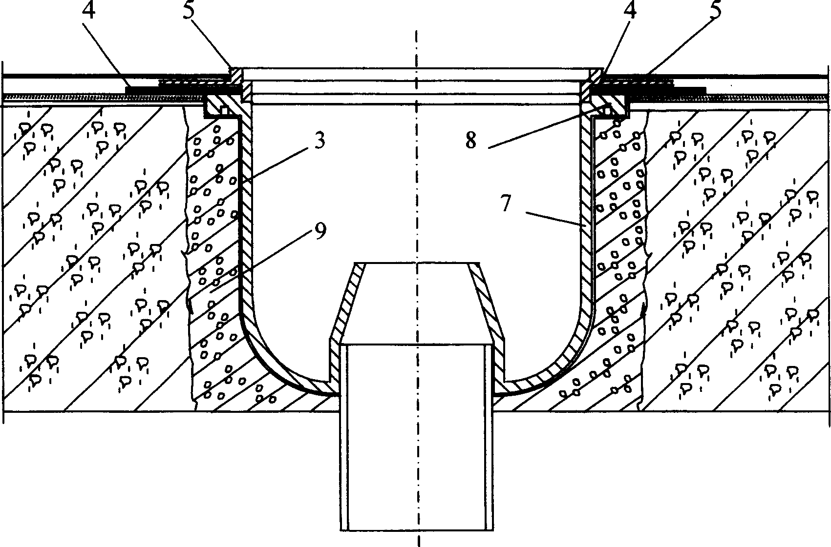
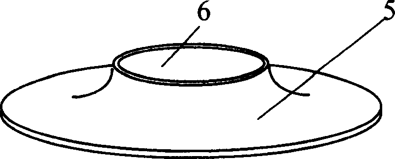
[0051] like figure 2 , Fill up between floor drain 7 and floor hole 2 with concrete 9 secondary pouring joints, when preventing from smearing sealing waterproof material above, sealing waterproof material flows downwards. Join the floor below the wide edge 8 of the floor drain 7, and apply the sealing waterproof material 4 with adhesive polyurethane waterproof material on the floor drain 7 wide edge 8 and the floor surface seam 3 positions connected, for Make the appearance of the polyurethane waterproof material have a fixed standard shape, and also use the circular "cross" shaping pressure plate 5 to compact the polyurethane waterproof material on the surface of the polyurethane waterproof material, so that the polyurethane waterproof material is the thinnest The distance is 2 to 4 mm. And the shaped pressure plate 5 is bonded and fixed on the surface of the p...
Embodiment 3
[0052] Embodiment 3, the method of doing large-area waterproof construction after the waterproof construction of the joint between the pipeline and the floor slab
[0053] Carry out construction by the content described in embodiment 1. Carry out large-area waterproof layer construction thereafter, apply polymer cement waterproof paint in a large area on the floor, and polymer cement waterproof paint is applied and overlapped on the surface of the shaped pressure plate 5 of the waterproof member. A large-area polymer cement waterproof coating is covered on the surface of the shaped platen 5. After the polymer cement waterproof coating is solidified and formed into a film, a continuous waterproof layer composed of a large-area waterproof layer and waterproof components is obtained.
PUM
 Abstract
Description
Claims
Application Information