Pneumatic control unit of excrement collecting system for bullet train

A technology for collecting and moving trains, applied in the field of collecting systems, can solve the problems of ineffective management, affecting the quality of train service, and maintaining maintenance work, so as to improve the integrity rate and reliability, save railway operating costs, and save maintenance hours. effect of cost

A technology for collecting and moving trains, applied in the field of collecting systems, can solve the problems of ineffective management, affecting the quality of train service, and maintaining maintenance work, so as to improve the integrity rate and reliability, save railway operating costs, and save maintenance hours. effect of cost

CN103303328AActive Publication Date: 2013-09-18ZHUZHOU CSR TIMES ELECTRIC CO LTD

Image

  • Pneumatic control unit of excrement collecting system for bullet train
  • Pneumatic control unit of excrement collecting system for bullet train
  • Pneumatic control unit of excrement collecting system for bullet train

Examples


Embodiment Construction

[0013] The present invention will be described in detail below in conjunction with the accompanying drawings and embodiments.

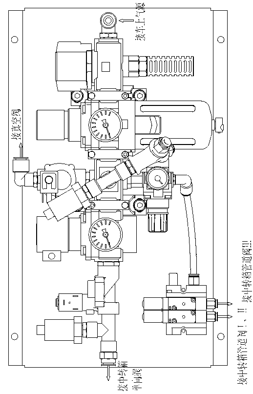
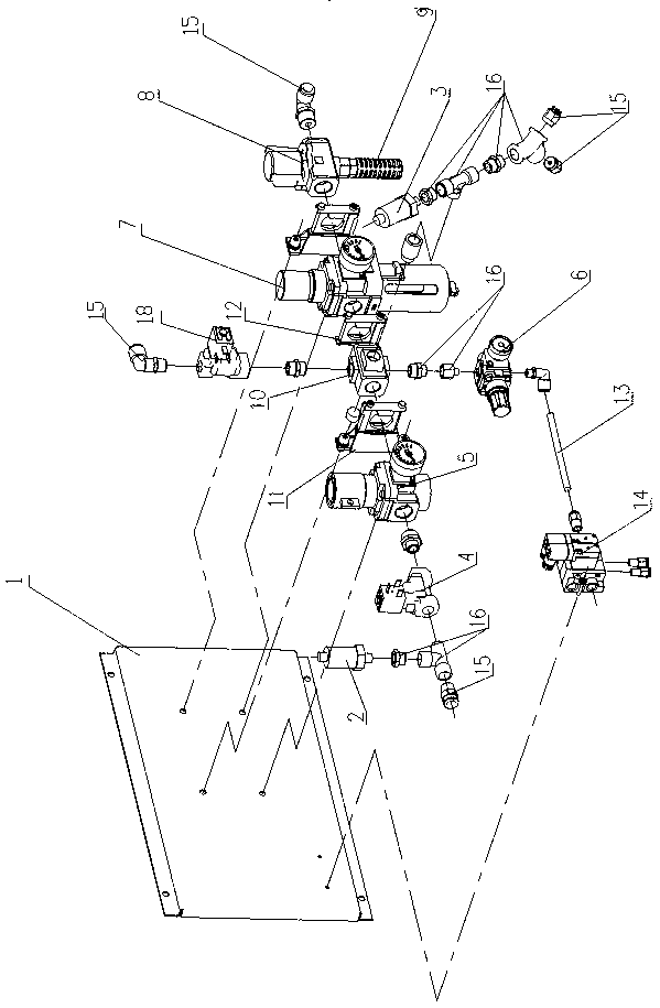
[0014] like figure 1 As shown, the pneumatic control unit of the feces collection system for motor vehicles includes a mounting plate 1, on which hexagonal nuts are welded for fixing various parts, and on the mounting plate 1, a stop valve 8, a main filter reducing valve are installed in sequence from right to left Pressure valve 7, four-way partition 10, 120kPa pressure regulating valve 5, A solenoid valve 4, 120kPa pressure detection switch 2, a vacuum solenoid valve 18 is set on the upper part of the four-way partition 10, and a vacuum solenoid valve 18 is set on the lower part of the four-way partition 10 450kPa pressure regulating valve 6, a 400kPa pressure detection switch 3 is set in the middle of the four-way partition 10, and a transfer box VII pipeline valve VIII control solenoid valve group 14 is set on the left side of the 450kPa pressure ...


PUM


Abstract

A pneumatic control unit of an excrement collecting system for a bullet train is mounted in a position close to the excrement collecting system, and comprises a mounting board, wherein a stop valve, a main filter pressure reducing valve, an adjusting valve A, an electromagnetic valve A, a transfer box pressure detection switch, a pressure regulating valve B, a transfer box pipeline valve control electromagnetic valve, a pressure detection switch B, an electromagnetic valve B and a non-return valve are mounted on the mounting board, and the stop valve, the main filter pressure reducing valve, the electromagnetic valve A, the electromagnetic valve B, the pressure detection switch B, the pressure detection switch B, a transfer box pipeline valve control electromagnetic valve set and a vacuum-pumping electromagnetic valve are controlled by an excrement collecting controller; after passing through the stop valve and the main filter pressure reducing valve through an air inlet, compressed gas is divided into four branches for supplying to all gas using units. According to the invention, a control unit is integrally mounted on a mounting board, the structure is compact, the occupied area is small, and the repair and maintenance are convenient.

Description

technical field [0001] The invention relates to a pneumatic control device for a vacuum defecation collection system of a railway motor vehicle, belonging to the technical field of defecation collection systems. Background technique [0002] All or most of the actuators of the air circuit control device in the existing defecation collection system are under discrete and individual control states. This system is very messy and cannot be managed effectively, and once a fault occurs, it is difficult to correctly judge the cause of the fault as soon as possible. The maintenance personnel can only constantly replace different parts according to personal experience until the work is normal. In extreme cases, it may be possible to replace the last component before troubleshooting. As a result, not only the maintenance cost and maintenance time of the vehicle are greatly increased, but also the integrity rate of the feces collection system is reduced. The vehicle is easy to run with...

Claims


Application Information

Patent Timeline
18 Sep 2013
Publication
CN103303328A
IPC
B61D35/00
Inventors
刘国亮; 祝起平