Permanent magnetic suspending shaft

A technology of magnetic suspension shaft and magnetic suspension bearing, applied in the direction of bearing, shaft and bearing, mechanical equipment, etc., can solve the problems of poor reliability, high cost and large volume, and achieve the effect of stable working state, light weight and large suspension force.

Inactive Publication Date: 2006-11-01
李岭群
View PDF1 Cites 2 Cited by
  • Summary
  • Abstract
  • Description
  • Claims
  • Application Information

AI Technical Summary

Problems solved by technology

The main disadvantage of this bearing is that the six degrees of freedom of the magnetic levitation shaft are electromagnetically controlled by the air gap sensor, which results in high energy consumption, poor reliability, large volume, and high cost.

Method used


Image

  • Permanent magnetic suspending shaft
  • Permanent magnetic suspending shaft
  • Permanent magnetic suspending shaft

Examples


Embodiment Construction

[0023] The following content is a detailed description of the present invention in conjunction with the accompanying drawings, but should not be construed as a limitation of the present invention.

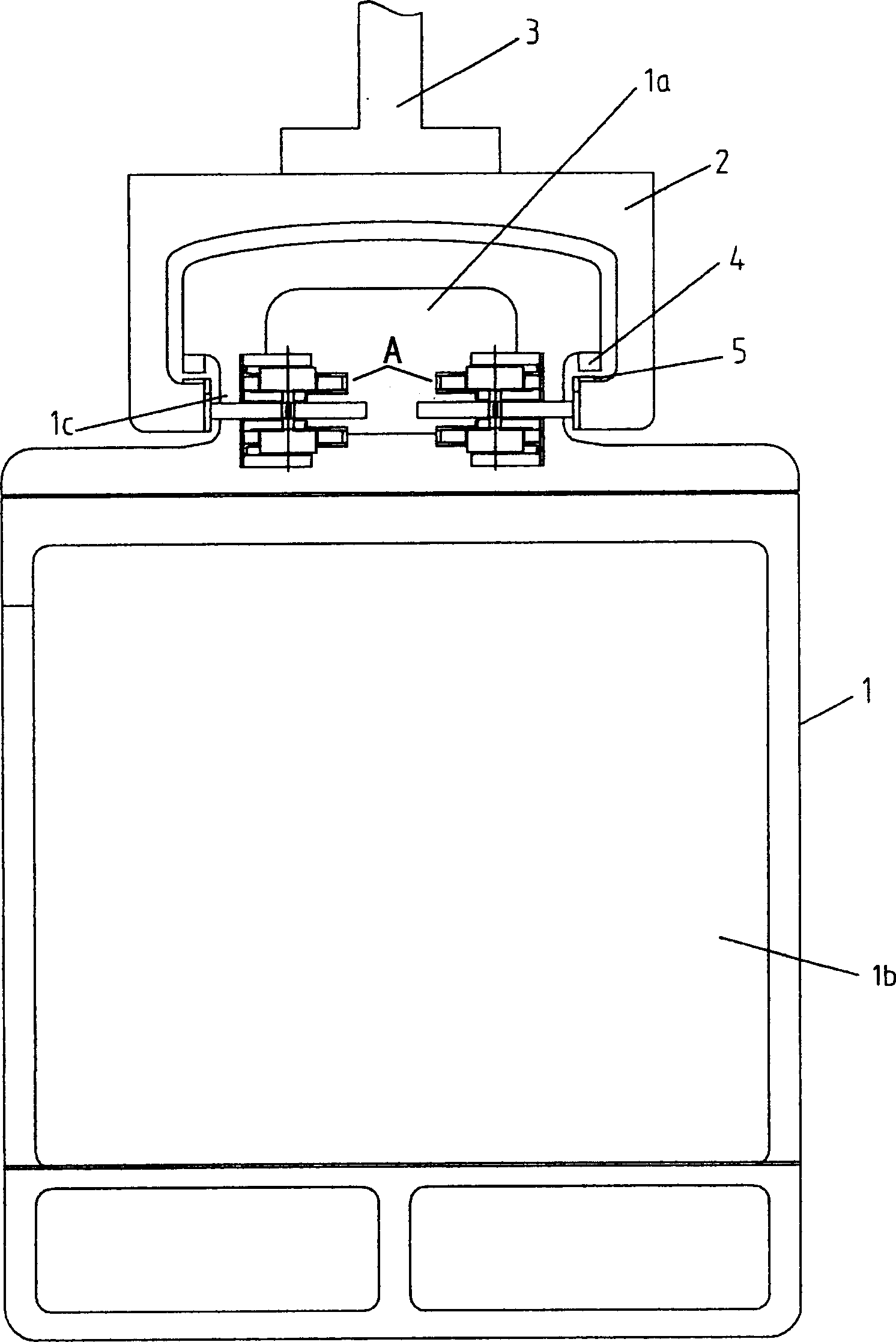
[0024] In order to facilitate the understanding of the working process of the permanent magnetic levitation shaft, please refer to figure 1 . The maglev train 1 is embedded in the bow-shaped suspension pillow 2, and the bow-shaped suspension pillow 2 is fixed below the I-beam 3. The train wing magnet 4 is corresponding to the same pole of the track magnet 5, and its magnetic field repulsive force will suspend the train. The train has an up-and-down structure, the upper part is the suspension power cabin 1a, and the lower part is the compartment 1b, and the guide wheel magnetic suspension shaft is fixed on the inner side of the suspension power cabin wall 1c, that is, the permanent magnetic suspension shaft A of the present invention.

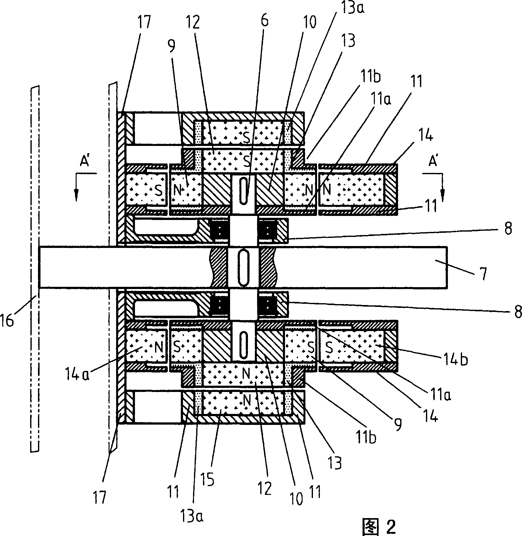
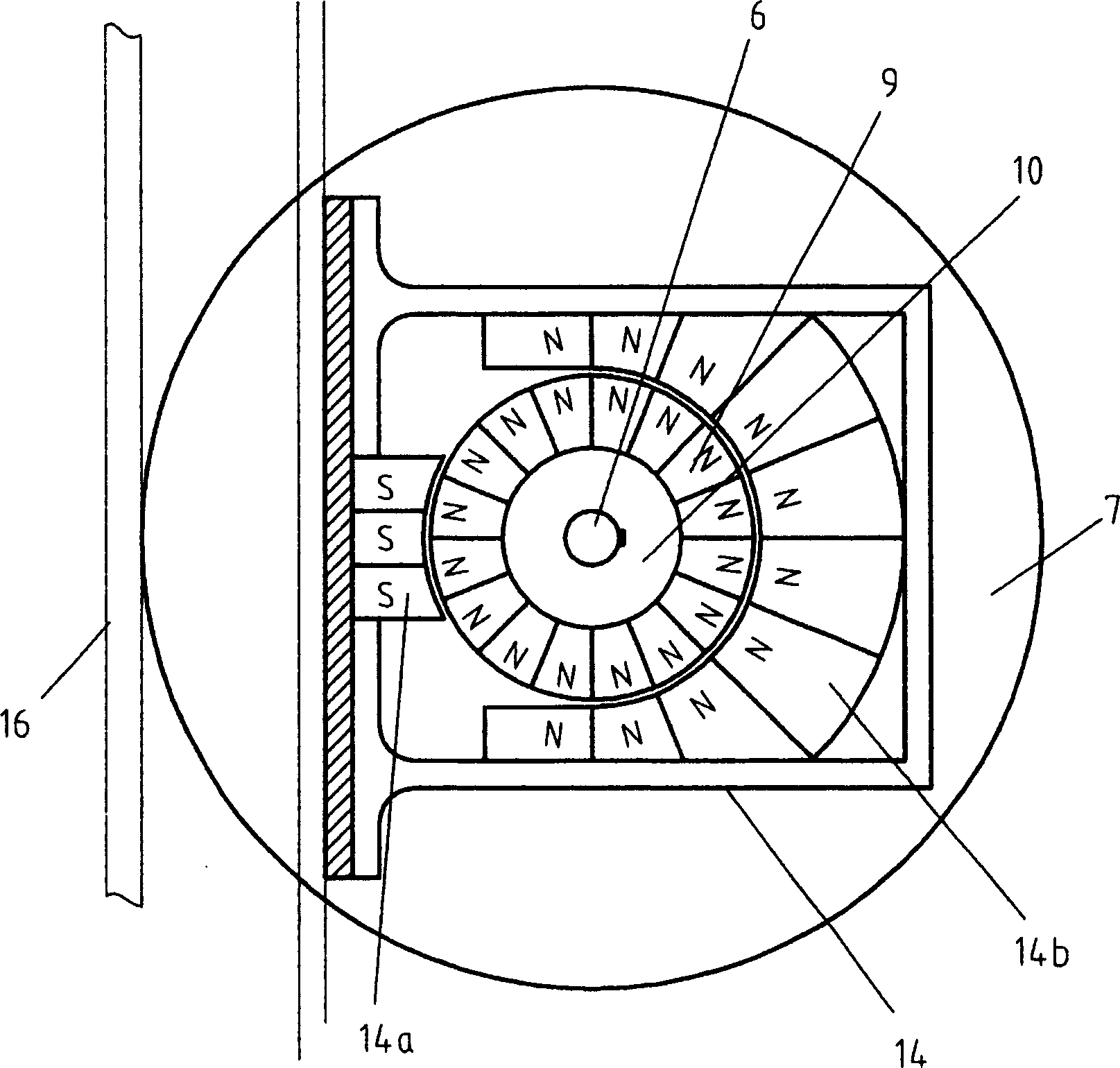
[0025] Then referring to Fig. 2,3, the cente...


PUM

PropertyMeasurementUnit
Thicknessaaaaaaaaaa

Abstract

A permanent-magnetic suspension shaft comprises a main shaft and a guide fixed pulley running on a guide rail and is symmetrically disposed on up and down sides of the guide fixed pulley. Two permanent-magnetic suspension bearings are fixed on a bearing seat around the permanent-magnetic shaft. An air gap is set between the permanent-magnetic shaft and the permanent-magnetic bearing. The upper and lower permanent-magnetic suspension terminals are fixed on the main shaft and the upper and lower permanent-magnetic spacing terminal bearings are fixed on the bearing seat.

Description

technical field [0001] The invention relates to the technical field of magnetic suspension shafts and bearings. Specifically, it relates to a technical system in which a permanent magnetic suspension shaft is in a suspended state along the direction of the wheel support force under the joint action of the repulsion and suction force of the bearing and the support force of the wheel. Background technique [0002] There is a certain air gap between the magnetic levitation shaft and the bearing, and there is no contact between them during the rotation. Therefore, it has no friction, no heat, high speed, low energy consumption and long service life when working. It is a recognized replacement technology and "green electromechanical product". Countries are competing to develop this technology field, and China has reached the world's advanced level in this technology field. For example, the 160xDs50M active magnetic suspension bearing technology developed by Shanghai University ...

Claims


Application Information

Patent Timeline
IPC IPC(8): F16C32/04
Inventor 李岭群
Owner 李岭群
Why Eureka
Try Eureka