Door handle device and keyless entry device having the same
A technology of door handles and handles, which is applied to the application of wing leaf handles, wing leaf handles, locks, etc., can solve the problems of reduced operability, cumbersome door opening/closing operations, etc., so as to improve the operating experience and make it easier Interference, effect of assembly performance improvement
- Summary
- Abstract
- Description
- Claims
- Application Information
AI Technical Summary
Problems solved by technology
Method used
Image
Examples
no. 1 example
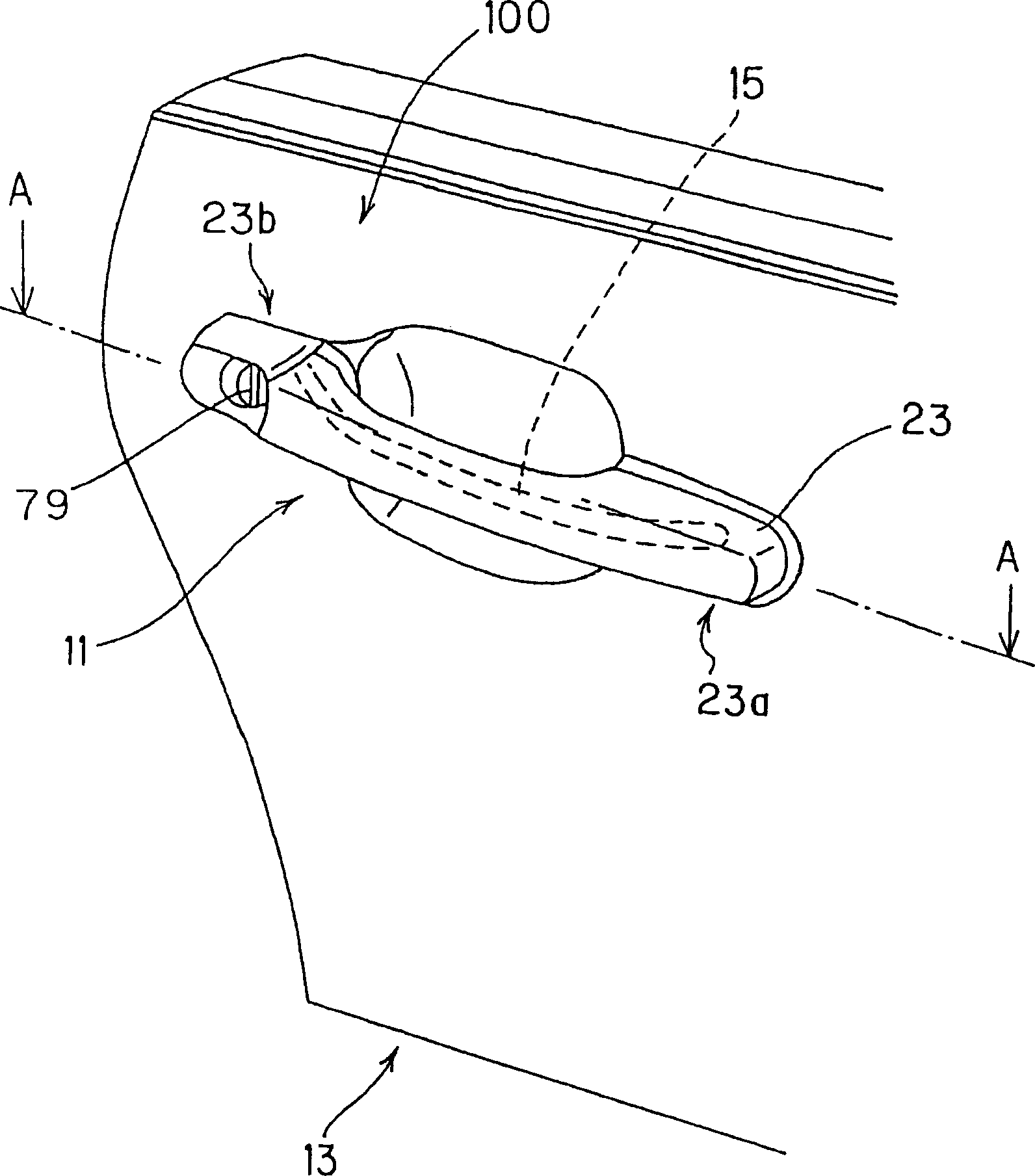
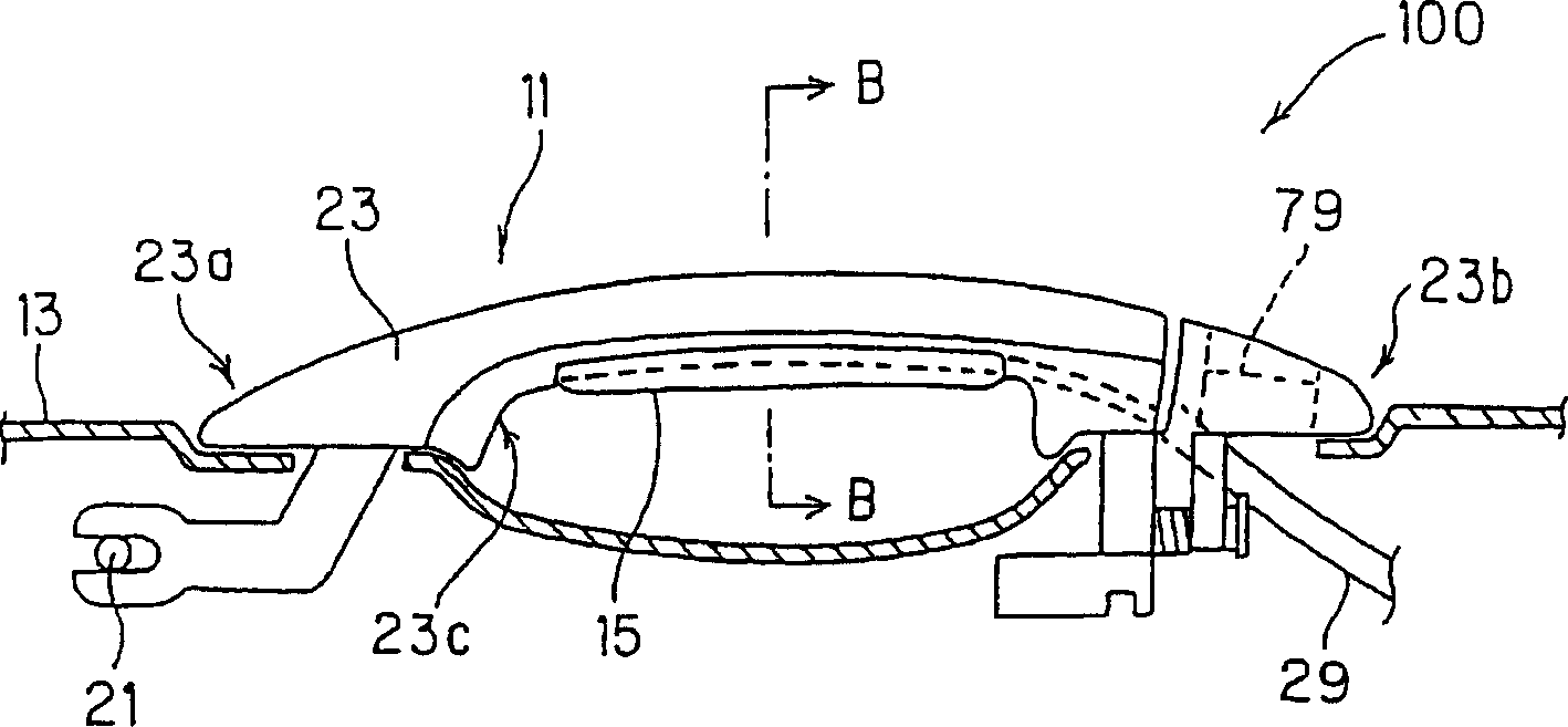
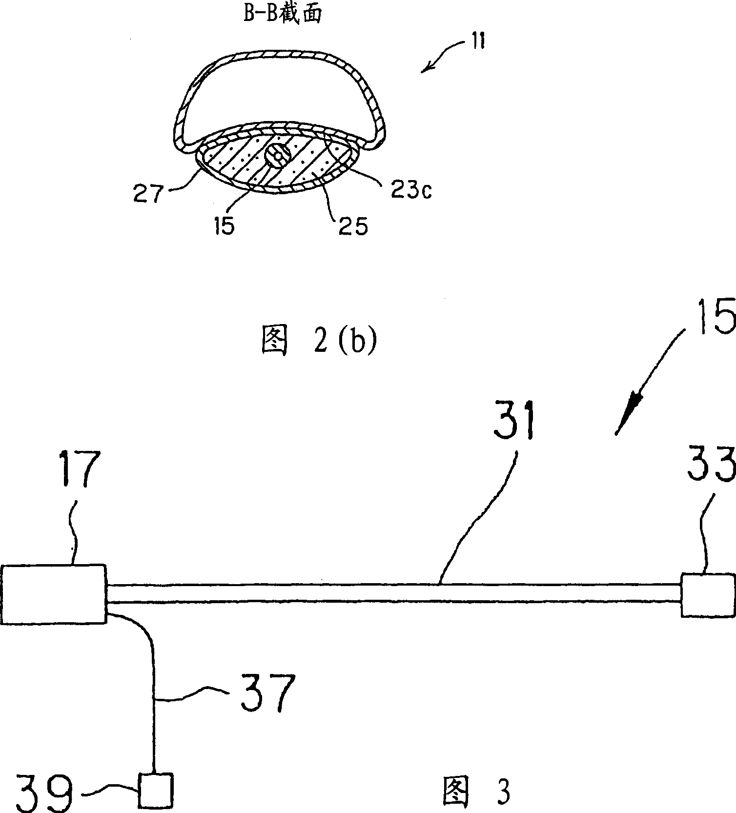
[0133] figure 1 is an external perspective view showing a door handle device according to a first embodiment of the present invention. Figure 2 is an internal structural view, where (a) shows figure 1 The A-A section in (b) shows the B-B section in Figure 2(a). FIG. 3 is a schematic structural view of the piezoelectric sensor shown in FIG. 2 . Figure 4 is a structural view of the piezoelectric element material shown in FIG. 2 . Figure 5 is the block diagram of the door handle device.
[0134] Such as figure 1 As shown, the door handle device 100 according to the first embodiment is provided to a door 13 having a handle 11 for opening / closing operation. A door lock device (not shown) for locking the opening operation of the door 13 can be opened by operating the handle 11 . The main structure of the door handle device 100 includes a piezoelectric sensor 15, which is formed by a piezoelectric element disposed on the handle 11 and having flexibility, and a control circ...
no. 2 example
[0169] Next, a door handle device according to a second embodiment of the present invention will be described below. Here, in the following embodiments, the same reference numerals are attached as Figure 1 to Figure 9 For the same components or parts as shown, repeated explanations about them are omitted here.
[0170] FIG. 10 is a sectional view showing a door handle device according to a second embodiment of the present invention. Figure 11 It is a view taken along line C-C in Fig. 10. Figure 12 is a plan view showing Variation 1 of the second embodiment in which the piezoelectric sensor is arranged near the support shaft. Figure 13 is a plan view showing Variation 2 of the second embodiment in which the tip of the piezoelectric sensor is inserted into the insertion hole of the handle main body. Fig. 14 is a plan view showing Variation 3 of the second embodiment, in which the handle main body is configured as a handle integrated in a door.
[0171] The door handle de...
no. 3 example
[0188] Next, a keyless entry system according to a third embodiment of the present invention will be described below.
[0189] Fig. 15 is a block diagram showing a keyless entry system according to a third embodiment of the present invention, in which (a) shows its schematic structure and (b) shows its main detailed structure. Figure 16 is a flowchart showing an operation procedure in the keyless entry system shown in FIG. 15 .
[0190] The keyless entry system 300 includes any one of the door handle devices 100, 200 described in the first and second embodiments and their variants (for example, the door handle device 100), installed in the The transmitter / receiver 91 on the vehicle side is shown, and the transmitter / receiver 93 is carried by the operator. The keyless entry system 300 is basically used to receive the password request signal transmitted by the vehicle side transmitter / receiver 91 at the mobile side transmitter / receiver 93 and then the vehicle side transmitter / ...
PUM
 Abstract
Description
Claims
Application Information
 - R&D
- Intellectual Property
- Life Sciences
- Materials
- Tech Scout
- Unparalleled Data Quality
- Higher Quality Content
- 60% Fewer Hallucinations
Browse by: Latest US Patents, China's latest patents, Technical Efficacy Thesaurus, Application Domain, Technology Topic, Popular Technical Reports.
© 2025 PatSnap. All rights reserved.Legal|Privacy policy|Modern Slavery Act Transparency Statement|Sitemap|About US| Contact US: help@patsnap.com


