
Clock distribution apparatus used for digital PET detector

A clock distribution and detector technology, applied in the field of medical imaging, can solve the problem of not being able to provide enough synchronous clock signals or reset signals, and achieve the effect of optimizing costs

Active Publication Date: 2017-09-15
苏州瑞迈斯科技有限公司
View PDF5 Cites 13 Cited by
  • Summary
  • Abstract
  • Description
  • Claims
  • Application Information

AI Technical Summary

Problems solved by technology

[0008] The purpose of the present invention is to provide a clock distribution device for digitized PET detectors, thereby solving the problem that a sufficient number of synchronous clock signals or reset signals cannot be provided in the prior art

Method used


Image

  • Clock distribution apparatus used for digital PET detector
  • Clock distribution apparatus used for digital PET detector
  • Clock distribution apparatus used for digital PET detector

Examples


Embodiment Construction

[0024] The present invention will be further described below in conjunction with specific embodiments. It should be understood that the following examples are only used to illustrate the present invention but not to limit the scope of the present invention.

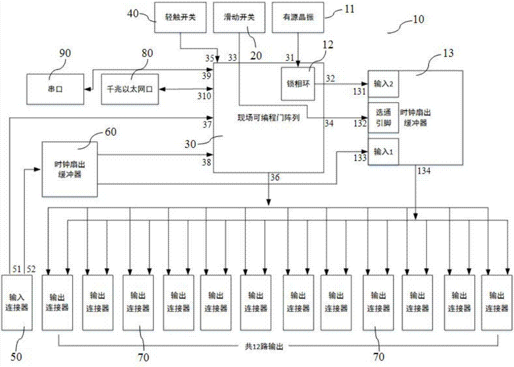
[0025] figure 1 It is a schematic diagram of a clock distribution device for a digitized PET detector according to an embodiment of the present invention, consisting of figure 1It can be seen that the clock distribution device of the present invention includes several clock modules 10, and each clock module 10 includes an active crystal oscillator 11, a phase-locked loop 12, a first clock fan-out buffer 13, a slide switch 20, a field programmable gate array ( Hereinafter referred to as FPGA) chip 30, tact switch 40 and output connector 70, wherein, active crystal oscillator 11 and phase-locked loop 12 are connected through pin 31, active crystal oscillator 11 generates clock signal and sends this clock signal to phase-lo...


PUM


Abstract

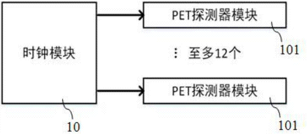
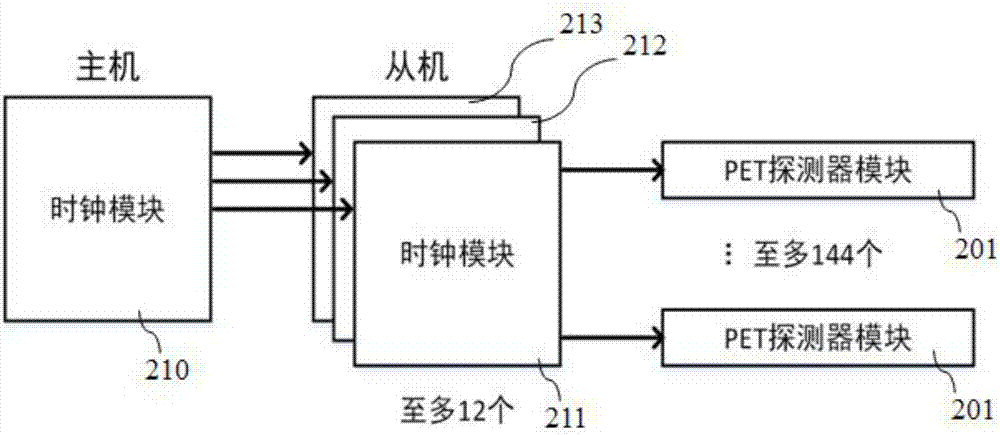
The invention provides a clock distribution apparatus used for a digital PET detector. The apparatus comprises at least one clock module. Each clock module comprises an active crystal oscillator used for generating a clock signal, a phase-locked loop which is in communication connection with the active crystal oscillator and is used for processing the clock signal and generating a first differential signal, a first clock fan-out buffer in communication connection with the phase-locked loop and a 12-output connector, an FPGA chip which is in communication connection with the 12-output connector and sends a second low-voltage differential signal generated by the FPGA chip to the output connector, a sliding switch which is connected with the FPGA chip to optionally send a relatively high or low level, a light touch switch which is connected with the FPGA chip to send a reset signal, and an input connector connected with the FPGA chip and the second clock fan-out buffer. According to the apparatus, at least 12 synchronous clock signals and synchronous reset signals can be provided, and the clock modules can be cascaded into a tree structure for providing more outputs; and the apparatus is wide in applicability.

Description

technical field [0001] The invention relates to a femtosecond clock distribution device in the field of medical imaging, more particularly to a clock distribution device for digitized PET detectors. Background technique [0002] PET (Positron Emission Tomography, Positron Emission Tomography) imaging technology is a relatively advanced clinical examination imaging technology in the field of nuclear medicine. More and more hospitals have begun to use clinical PET machines for auxiliary diagnosis and treatment. In PET imaging technology, the ideal clock signal is a periodic square wave with a certain amplitude and frequency, which is used to drive various electronic chips containing sequential logic, such as ARM (Acorn RISC Machine) processors, FPGAs and CPUs, etc. , the measurement unit of the frequency of the clock signal adopts the SI unit hertz (Hz). The reset signal refers to a period of high or low level, which is used to reset the sequential logic. For the digital PET ...

Claims


Application Information

Patent Timeline
IPC IPC(8): G06F1/10G06F1/12G06F1/24H04J3/06
CPCG06F1/10G06F1/12G06F1/24H04J3/06H04J3/0644
Inventor 奚道明吴杰梅雄泽刘苇
Owner 苏州瑞迈斯科技有限公司
Learn More