Supercharge Your Innovation With Domain-Expert AI Agents!

Guide rail structure for Y-axis carriage and cross beam of numerically controlled planer boring/milling machine

A beam and Y-axis technology, applied in the field of CNC machine tools, can solve the problems of multiple manual grinding of the joint surface between the pressure plate and the lower guide rail surface, and achieve the effects of guaranteed running accuracy, guaranteed machining accuracy, and reliable running accuracy

Inactive Publication Date: 2006-11-08
JIANGSU HENGLI MACHINE TOOL
View PDF0 Cites 6 Cited by
  • Summary
  • Abstract
  • Description
  • Claims
  • Application Information

AI Technical Summary

Problems solved by technology

[0004] The technical problem to be solved by the present invention is to overcome the deficiency in the prior art that requires multiple times of manually grinding the joint surface of the pressure plate and the lower guide rail surface, and to provide a guide rail structure for the Y-axis carriage and the beam of the CNC gantry boring and milling machine

Method used


Image

  • Guide rail structure for Y-axis carriage and cross beam of numerically controlled planer boring/milling machine
  • Guide rail structure for Y-axis carriage and cross beam of numerically controlled planer boring/milling machine

Examples


Embodiment Construction

[0017] Embodiments of the present invention are described in further detail below in conjunction with the accompanying drawings:

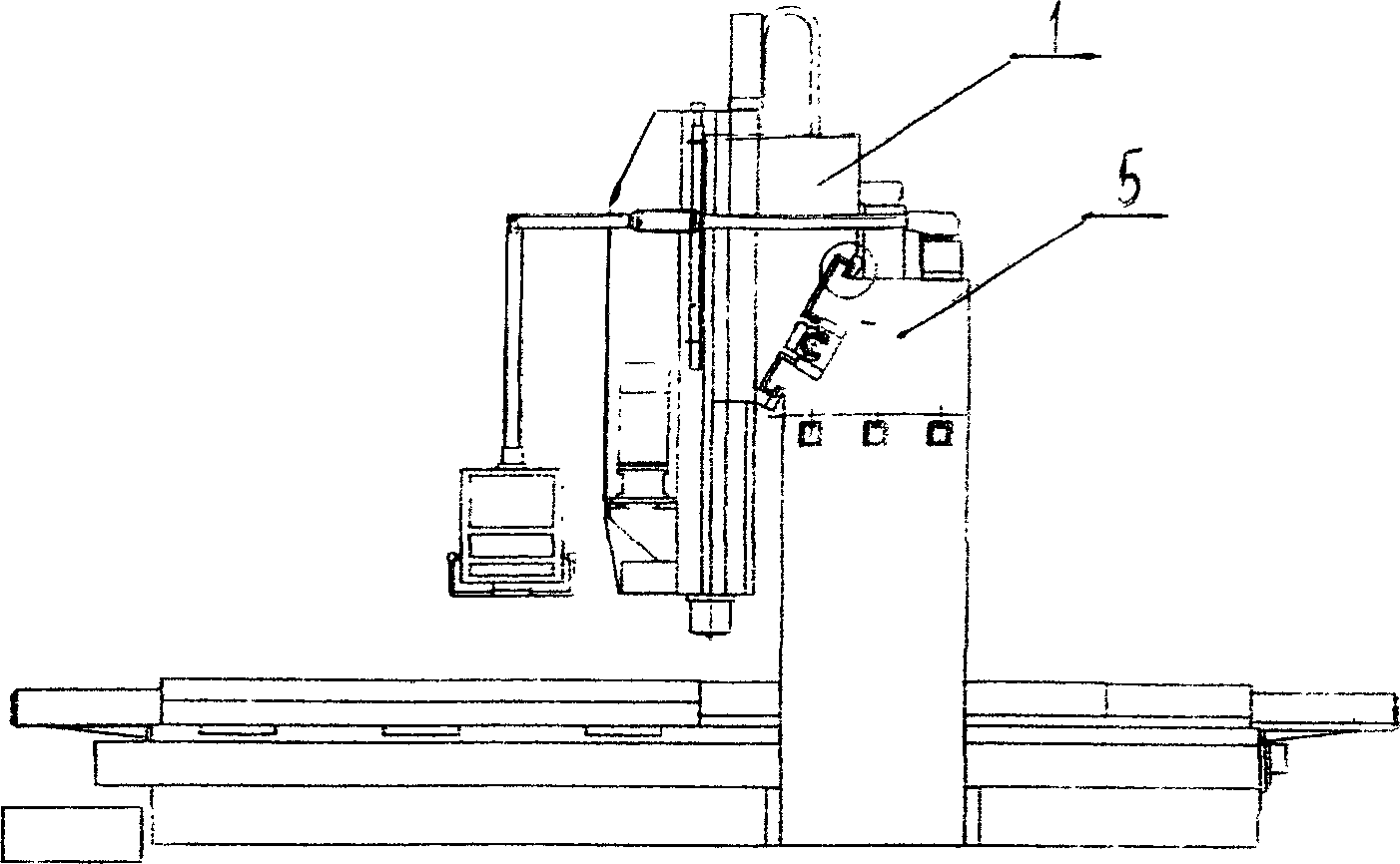
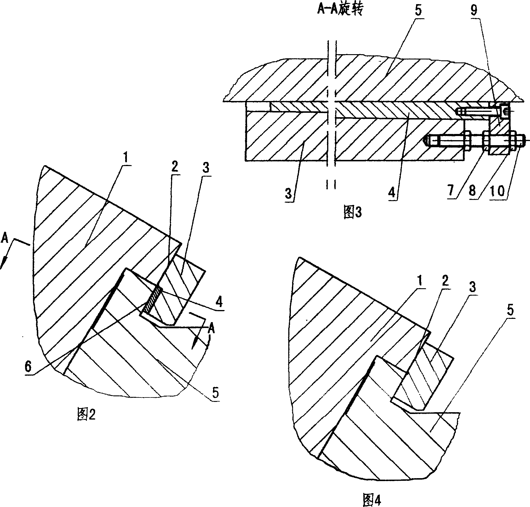
[0018] The present invention is an improvement to the prior art - VMC2000 CNC gantry boring and milling machine and machining center, which is symmetrically located on both sides of the 30° inclined guide rail where the Y-axis carriage 1 and the beam 5 cooperate. The present invention includes a Y-axis carriage 1 , a beam 5 , a pressing plate 3 and a wedge 4 . The pressure plate 3 is arranged on the lower side of the lower guide rail surface 2 of the Y-axis carriage and the lower guide rail surface 6 of the crossbeam, and a notch groove with an "L" shape in section is provided on the pressure plate 3 . The pressure plate 3 is closely attached to the lower guide rail surface 2 of the Y-axis carriage. The notch of the pressure plate 3 is set on the lower side of the lower guide rail surface 6 of the beam. In the notch groove of the pressure plate 3....


PUM


Abstract

The present invention relates to the improvement of available VMC2000 numerically controlled planer boring / milling machine, and is especially guide rail structure for Y-axis carriage and cross beam of numerically controlled planer boring / milling machine. The present invention includes Y-axis carriage, cross beam and clamping plate, and features the wedge between the lower cross beam rail and the clamping plate, and the adjustable relative position of the wedge with a regulator. The present invention has the advantages of convenient regulation of the gap between the clamping plate and the lower rail plane of the Y axis with screw, omitting the corresponding repair, easy machine assembling to reach required precision.

Description

technical field [0001] The invention relates to a numerical control machine tool, in particular to a guide rail structure of a Y-axis carriage and a beam of a numerical control gantry boring and milling machine. Background technique [0002] The CNC gantry boring and milling machine adopts the worktable movement, the gantry fixed beam frame structure, the X-axis worktable moves horizontally, the Y-axis carriage moves horizontally on the beam, and the Z-axis ram-type spindle head moves vertically on the carriage. The Y-axis adopts a 30° inclined guide rail to improve the force performance and ensure good rigidity and precision retention of the whole machine. The guide rail structure of the Y-axis carriage and the beam of the CNC gantry boring and milling machine includes the Y-axis carriage, the beam and the pressure plate, which are located on both sides of the 30° inclined guide rail that the Y-axis carriage and the beam match. [0003] At present, the lower guide rail str...

Claims


Application Information

Patent Timeline
IPC IPC(8): B23Q1/25B23Q1/01
Inventor 孙德洲
Owner JIANGSU HENGLI MACHINE TOOL
Features
  • R&D
  • Intellectual Property
  • Life Sciences
  • Materials
  • Tech Scout
  • Unparalleled Data Quality
  • Higher Quality Content
  • 60% Fewer Hallucinations
Learn More